internal cab dimensions are 28.5 x 14 x 12.5
some is taken up by pvc cap mid enclosure, not sure of exact volume.
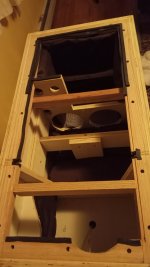
single port that is 4 inch ID and 10 inches long.
here's my braces I added, hopefully the one across the baffle at the bottom helps. I'd ignore the gasket tape, never looks like that.
some is taken up by pvc cap mid enclosure, not sure of exact volume.
single port that is 4 inch ID and 10 inches long.
here's my braces I added, hopefully the one across the baffle at the bottom helps. I'd ignore the gasket tape, never looks like that.
Attachments
Thanks - yes I went back to your first post... should have checked there🙂
So - you should be getting an F3 ~ 30Hz with the alignment (roughly 85L minus midrange enclosure - for a maximially flat - EBS alignment)
I'm sorry but I now doubt my quasi-anechoic approach. Whether I lowered the port response too much (as I thought aligning tails was the correct approach between woofer near field and port)... either way, my estimated anechoic F3 of 47HZ is way too high
Two other things I thought of after posting #320...

- As I mentioned in post #283, merging the nearfield and port is nice to confirm the box model but is not going to effect the crossover. If you have good TS parameters, have a good estimate of net volume after driver, port and bracing, then you can confirm the port tuning with the impedance sweep and then box modelling programs are very good and you probably have a good idea of the SPL from 100-150Hz and below. I'm pretty sure VituixCAD has the option to merge the farfield with the box simulation as the low frequency part.
- But the "merging" is taking place somewhere between 200Hz and 400Hz, and THIS IS in the area of the crossover, so getting it significantly wrong will matter. Even after gating the farfield, there was not a good smooth area between the farfield and nearfield to do the merge, so I just took a reasonable guess. When trying to choose the window, it was not clear where the first reflection was. In the image below, blue is wafflesomd's IR and red is my measure of an SB16PFCR25-8. For the SB16 there is a pretty clear first reflection right around 4.5ms.
This most likely is some resonance in the chain. T is about 0,5ms, so around 2kHz. Is the woofer and enclosure combo causing this?
Just insert the diameter or the Sd of woofer and port in the corresponding column.No, but only because I'm pretty sure VituixCAD does it automatically "somehow".
I was really hoping bracing would have affected the low impedance blip but no, really wish I could track it down.
I think I can deal with some of the cons of the design, but not this resonance down there. Urge to toss parts in new MDF enclosure rising. Perhaps this isn't really something worth getting lost in the measurements over.

I think I can deal with some of the cons of the design, but not this resonance down there. Urge to toss parts in new MDF enclosure rising. Perhaps this isn't really something worth getting lost in the measurements over.
Last edited:
With virtually no response blips in your near field measurements I would forget about that 160Hz thing. The burst decay plots of woofer and port show next to nothing. As others including yourselves have pointed out, it’s probably the room.

Thanks - yes I went back to your first post... should have checked there🙂
So - you should be getting an F3 ~ 30Hz with the alignment (roughly 85L minus midrange enclosure - for a maximially flat - EBS alignment)
I'm sorry but I now doubt my quasi-anechoic approach. Whether I lowered the port response too much (as I thought aligning tails was the correct approach between woofer near field and port)... either way, my estimated anechoic F3 of 47HZ is way too high
Shall I monitor the discussion and wait for things to get ironed out or can I use the merged response posted for xover design?
In the mean time I've gotta get the other cabinet braced the same and install a new port in one, should be easy.
Go ahead with crossover design. why? The low frequency extension (and resulting minimum phase response) will be no different between versions we've published - since I believe we are looking at a 89dB woofer at around your assumed crossover point (200-300 Hz?). If you want confirmation - look at extracted / derived phase for both versions posted above - and you are likely to see extremely similar phase responses around your intended crossover region (and similar frequency responses).\
Re the 160Hz blip - I would experiment with damping materials. these can do quite a lot (be mindful of restricting airflow to the port however and some damping will have a negative effect on low bass sensitivity).
Edit: I'm not convinced my sim bass extension frequency response is correct, but neither I am convinced a4eaudio's is either. his has a f3 ~ 25Hz which is lower than the expected F3 of ~ 30Hz for your 85L box with FB=29Hz, plus his has the nearfield hump which could be inherent in the driver or overstated port measurement (not scaled). I'm not criticising anyone, nor how VituixCAD works (which should be near 100%), but I haven't used Vituixcad to apply the merge.
Last edited:
PS: how are you intending to determine relative acoustic (Z) offset of drivers for crossover design? You can estimate distances but another approach I've found very useful is the "summed driver" measurement then aligning Z of the individual driver responses until they result in the summed response. Let me know if you want more info,.
Go ahead with crossover design. why? The low frequency extension (and resulting minimum phase response) will be no different between versions we've published - since I believe we are looking at a 89dB woofer at around your assumed crossover point (200-300 Hz?). If you want confirmation - look at extracted / derived phase for both versions posted above - and you are likely to see extremely similar phase responses around your intended crossover region (and similar frequency responses).\
Re the 160Hz blip - I would experiment with damping materials. these can do quite a lot (be mindful of restricting airflow to the port however and some damping will have a negative effect on low bass sensitivity).
I tried basically everything and the only things that affected the impedance blip were covering the port in rubber and basically filling the entire thing with a bunch of pillows of various materials like memory foam, which isn't really going to work with a ported speaker. I added a good chunk of bracing and that didn't do anything to it. The whole cabinet had 2" and in some places 4" of OC703. I feel like I've tried just about everything at this point. Removed the port of one speaker and that didn't have any effect. This problem was my main motivation to rebuild.
PS: how are you intending to determine relative acoustic (Z) offset of drivers for crossover design? You can estimate distances but another approach I've found very useful is the "summed driver" measurement then aligning Z of the individual driver responses until they result in the summed response. Let me know if you want more info,.
I'd definitely need more info and help on this one. I was assuming that the offset would kind of be built into the measurements but you're saying vcad needs the offset for xover design.
Lots to learn but at least making progress.
I'd probably just ignore the blip at this point. As someone said, either a measurement artifact, driver mounting resonance maybe? In anycase, it's unlikely to go away given the diverse treatments you've applied. whether this blip is audible? I don't know.I tried basically everything and the only things that affected the impedance blip were covering the port in rubber and basically filling the entire thing with a bunch of pillows of various materials like memory foam, which isn't really going to work with a ported speaker. I added a good chunk of bracing and that didn't do anything to it. The whole cabinet had 2" and in some places 4" of OC703. I feel like I've tried just about everything at this point. Removed the port of one speaker and that didn't have any effect. This problem was my main motivation to rebuild.
If it is port related, there are some "stub / T section" solutions that can be used to reduce modal resonances in the pipe. Beyond my area of knowledge and you may be chasing minutia here (bigger fish to fry = eg. a good crossover!)
Re crossover...
Whenever we take measurements and either:
1. Do not use a timing reference (that is loopback to measure actual phase) - requiring an XLR mic and same position volume / / impulse across all driver measurements.
2. Alter the frequency response (in any way - like I've been doing above - to get quasi anechoic response)
We can't rely on the measured phase between drivers meaning our crossover will be using poor phase data = bad design.
What we then do is check the boxes in crossover tools to use "derived or extracted" phase response for each driver. Since this "new" phase response has no relativity - we need to work out the acoustic offset of each driver so the phase response is correct resulting in accurate crossover simulation. The acoustic offset is the "Z" value for each driver in your crossover and is used to offset the vertical axis to account for non time aligned drivers (e.g. woofer voice coil / dustcap set back from tweeter on a flat baffle).
What I do is measure driver pairs. that is - wire both woofer and midrange in parallel and do a sweep. Then wire midrange and tweeter in parallel and do another sweep (don't move the mic between these 2 measurements). Ensure when doing the sweep you don't overload the tweeter (either start from 400Hz or keep power within 1v output).
The output will be wonky and that is fine. What we want to do is then load your derived individual frequency responses into a crossover simulator - and adjust the Z offset on the woofer so that the individual summed responses match the wonky response = you have your offset.
Do the same for the midrange / tweeter pair.
Once you have the midrange offset for the midrange / tweeter pair, add this midrange offset to the woofer Z offset (since the woofer / midrange was done without tweeter). I'm not doing a good job explaining this... some pictures would be useful (but not handy).
I'd probably just ignore the blip at this point. As someone said, either a measurement artifact, driver mounting resonance maybe? In anycase, it's unlikely to go away given the diverse treatments you've applied. whether this blip is audible? I don't know.
If it is port related, there are some "stub / T section" solutions that can be used to reduce modal resonances in the pipe. Beyond my area of knowledge and you may be chasing minutia here (bigger fish to fry = eg. a good crossover!)
I was going to try a few things, but yes I'd like to take care of it later. I can play with just about anything with the port as long it's usin the sched 40 4" pvc pipe. I was gonna try some holes, and maybe try to cut out a half oval shape in the end and replace it with some rigid felt ala this genelec speaker. I don't know if lining the inside of the port with some felt would help, kinda seems like I just have to try things and see how they go but at least it's easy with this build.
https://www.audiosciencereview.com/...enelec-8351b-teardown-2nd-disassembled.22785/
Whenever we take measurements and either:
1. Do not use a timing reference (that is loopback to measure actual phase) - requiring an XLR mic and same position volume / / impulse across all driver measurements.
2. Alter the frequency response (in any way - like I've been doing above - to get quasi anechoic response)
can one simply avoid the methods you mentioned by using a timing reference? My interface would have no problem with this. When I ran the speaker active I think 0.04ms was the difference between the mid and tweeter, surprised how audible that difference was.
I think you explained things fine Dave. A lot to take in and I usually have to read things a few times to get it, putting things into practice is the ultimate in understanding though.
Hi,
yeah with two channel measurement the other channel works as timing reference and distance is imprinted into the response. You still need to be careful and keep relative accuracy on things, like known distance from speaker to mic and position of the mic in relation to the speaker. You now know what the data is, and the data should be valid to be used as basis in simulator.
There will be some error with home measurements compared to anechoic chamber stuff due to gating for example, and multiple steps in the process that could yield some error. Luckily its not too bad, and basically best you can do at home. Although, there is thread by a signal processing wizard here on the forum, using few mics making an array and then some matlab stuff he was able to extract reflections out, if I remember, reducing error due to home environment.
Worse than error is uncertainty, you have to learn the stuff yourself with million things that can go wrong so some persistence is needed, its really not that hard or difficult to get consistent results, just takes some time to build up experience and confidence, some practice.
Out of curiosity, what was your listening distance? 🙂 I think I'm also able to hear timing between ways as a spatial effect but only with short listening distance. Listening otherside of the room I was shocked I could put multiple millisecond delay to tweeter and hear about no difference, until distinct secondary sound. Active systems are great, realtime adjustment.I ran the speaker active I think 0.04ms was the difference between the mid and tweeter, surprised how audible that difference was.
I sit about 6 to 8 ft away from the speakers. The sound just kinda becomes more coherent, like the tweeter and mid are one source we with the delay.
I'm not sure if I'm sold on the d27 tweeter, I'm going to toss in a dx25 and see how that works. something about deep loading the dome with walls around it sounds like a bad idea to me but I'm not a driver designer. I have some spare dx25 so its a free experiment at least.
Sounds like I might have to take new set of measurements eventually with updated techniques.
bracing matches now, good chunk of work for simple wood pieces. going to order some other dampening materials to replace the fiberglass, stuff is just a pain to handle.
You mean the D27TG35-06 and the DX25TG59-04? These won’t differ much, apart from the impedance. The correct dome loading actually is of quite some importance, Vifa/Tymphany know what they do in this respect. Don’t let possible bias mislead you.
Noted, I don't really find any of these flat faceplate tweeters to sound that good in general TBH.
- Home
- Loudspeakers
- Multi-Way
- Help with 3 way