A quick look it's OK. Not shown, but you will heat sink the cascodes, right?
I'm really do not have consider heatsinks for the cascodes, a least until now, I had build an F5 Turbo V3 a few months ago with +/- 41v power supply without heat problems on cascodes, but I'm open to incorporate any suggested impovement.
Thanks for taking your time to help me.
Regards,
Alejandro
Exactly. One of the many advantages of balanced pieces is the halved voltage rails. But you know that.
G
G
Or the 2SC4793 / 2SA1837 pair - they're my new favorites.
G
I have some 2SA1837 that left from the F5 Turbo V3 build, can I directly replace the BC556?
JFET part numbers are so confusing compared to our good old MOSFET friend IRF610 🙂
I'm very intreagued to hear the difference in sound character these changes will make.
...one could add FET sockets when removing the 610s - make switching back and forth between LPTs easy? Wire the two differences to a switch? 😎
I'm very intreagued to hear the difference in sound character these changes will make.
...one could add FET sockets when removing the 610s - make switching back and forth between LPTs easy? Wire the two differences to a switch? 😎
Hi moe29,
Here are my impressions of the sonic differences going from irf9610's to 2SJ109's (or 2sj74's). Keep in mind that these are just one mans opinion.
http://www.diyaudio.com/forums/pass-labs/73543-ax100-100w-aleph-x-monoblocks-44.html#post1438413
As an aside I gave away the original MOSFET's to a fellow DIYA member a couple of years ago.
At BA 2012 the AX100J's spent about 45 minutes in Nelson's demo system in the Pass room. At one point he walked up to me and said that it had been a long time since he had listened to an amp like mine with a MOSFET front end and that he was surprised at how good it sounded. I then had to tell him that he wasn't listening to MOSFET's.
Graeme
Last edited:
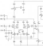
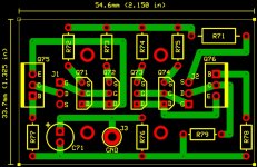
New Schema & Board w/2SA1837 Cascodes and Heatsinks
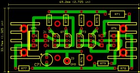
I had changed the BC556 by the 2SA1837 for cascodes and incorporated heatsinks. The board is now bigger and heavy, so I added four holes to fix it to the monting holes of the IRF9610's heatsinks on the mainboard.
Also R71 (1w) & C71 have a bigger size on the daughterboard to support more alternatives of resistors and capacitors.
Thanks for all help I have received.
Alejandro
Attachments
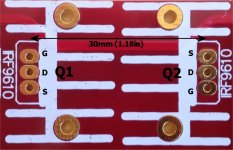
The 2SA1837 are enough bigger to use it without heatsinks, it's a good new for me, I really didn't hope so.
Now I need to draw the board without heatsinks.
Thanks Zen Mod.
Now I need to draw the board without heatsinks.
Thanks Zen Mod.

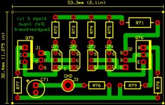
JFet daughterboard PCB w/2SA1837 cascodes w/o heatsinks (larger pads/same holes)
I had some limitations in the PCB software with the pads sizes and holes sizes combinations, I had increased the pad size keeping hole size where possible.
Regards,
Alejandro
I had some limitations in the PCB software with the pads sizes and holes sizes combinations, I had increased the pad size keeping hole size where possible.
Regards,
Alejandro
Attachments
OK , do what's possible
point is that , with larger pads , entire pcb is of greater quality and durability
when pads are small , sometimes is enough to just take a look of it , and solder could break
point is that , with larger pads , entire pcb is of greater quality and durability
when pads are small , sometimes is enough to just take a look of it , and solder could break
You really should make all your trace angles 45 or 90 degrees. PC board layout is part of what I do for a living and odd ball angles are not cool.
This will clean up a couple of places where the traces potentially run too close to each other. I don't know what the design rules are for your fabricator - but I'm just saying.
Graeme
This will clean up a couple of places where the traces potentially run too close to each other. I don't know what the design rules are for your fabricator - but I'm just saying.
Graeme
You really should make all your trace angles 45 or 90 degrees. PC board layout is part of what I do for a living and odd ball angles are not cool.
This will clean up a couple of places where the traces potentially run too close to each other. I don't know what the design rules are for your fabricator - but I'm just saying.
Graeme
I'm just starting with PCB design, all comments are really welcome. I agree with you, the traces with odd angles are ugly and maybe they do not meet the clearance area between traces that fabricator states. I'm using a free PCB/Schematic application from ExpressPCB - Free PCB layout software - Low cost circuit boards - Top quality PCB manufacturing, it's really easy to use and has online order at a "reasonable" price for small orders, it lacks of the advanced features of professional apps, but it's a good for starters like me.
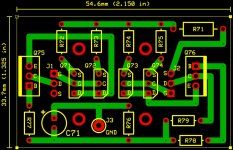
I had re-revised the PCB layout, now with only 90 degrees angles, Q75 rotated, more symmetry between left & right sides, the 4 holes for fix the daughterboard to the mainboard where also removed, some traces re-routed.
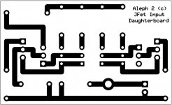
Attached you will find the new layout picture and also an image of only the bottom layer (copper side, not mirrored).
Thanks,
Alejandro
Attachments
That looks much better. Very nice.
Please note - I'm just commenting on the way it looks. I didn't check the layout against the schematic.
Please keep us posted as you build and test this.
Graeme
Please note - I'm just commenting on the way it looks. I didn't check the layout against the schematic.
Please keep us posted as you build and test this.
Graeme
That looks much better. Very nice.
Please note - I'm just commenting on the way it looks. I didn't check the layout against the schematic.
Please keep us posted as you build and test this.
Graeme
I'm still waiting for a answer from Spencer of FetAudio for the Jfets, also I try another source with no answer until today. I have enough LSJ74 from diyaudio store, but they match is poor. For the PCB I'm still looking locally for someone that could made it, if I not I will order from PCBexpress. I have all other parts in my house stock.
I will keep posting news as soon as happens.
Regards,
Alejandro
- Status
- Not open for further replies.
- Home
- Amplifiers
- Pass Labs
- Help wanted: Jfet front-end for Aleph 2