also, a note.
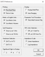
why does DATS list (10khz) next to LE? Isnt this suppossed to be measured at 1khz?
why does DATS list (10khz) next to LE? Isnt this suppossed to be measured at 1khz?
also, a note.
why does DATS list (10khz) next to LE? Isnt this suppossed to be measured at 1khz?
I am a rookie here but set up DATS per PE's instructional video here. I am confident everything is configured correctly.
https://www.youtube.com/watch?v=dARRX-tZpg4
His screen is showing the same thing so I am assuming all is well. I went through the setup and calibration and measurement multiple times all with the same results.
Last edited:
just seems odd, and would explain the seemingly consistent "lower than normal LE" I've seen posted.
just seems odd, and would explain the seemingly consistent "lower than normal LE" I've seen posted.
Good eye, hopefully Brian can explain.
also, a note.
why does DATS list (10khz) next to LE? Isnt this suppossed to be measured at 1khz?
DATS can be configured to display Le at 1kHz or 10kHz under the "Preferences".
I use the 1kHz setting for subwoofer duty.
Attachments
there we go. mind reposting the LE value for 1khz?
I can tonight.
PE got back to me really quickly with this reply.
Looks like they failed to notice that measured Fs = published Fs. What they described, i.e. "break-in", would also impact Fs, so the fact that it measures as published basically rubbishes their response. All of the parameters have dependencies on each other. None can change without corresponding changes being observed in the others.
So what is this? A case of inferior magnet material or? Half a** basket install?
Seeing that Fs is on spec, I'm going to guess that there's not enough "B" in the BL... 🙂
I responded to PE saying I broke the driver in and sent them my dats screen shots and sims. Here is the latest reply.
Breaking it in longer while in the cabinet is going to **** off the dog. 🙂 I already ran it out of the box at 38hz at a good level for over 30 mins.
Thanks.
Any guidance on if this is sound advice or any suggestions on how I should respond would be greatly appreciated.That is a start, but I would really give it a bit longer, These are fairly stiff drivers to start with. I would also load it in the actual box and give it a listen as modeling is great to getting an idea of the loading, but the real sound in a room is generally going to be a little different.
Breaking it in longer while in the cabinet is going to **** off the dog. 🙂 I already ran it out of the box at 38hz at a good level for over 30 mins.
Thanks.
Last edited:
I responded to PE saying I broke the driver in and sent them my dats screen shots and sims. Here is the latest reply.
Any guidance on if this is sound advice or any suggestions on how I should respond would be greatly appreciated.
Breaking it in longer while in the cabinet is going to **** off the dog. 🙂 I already ran it out of the box at 38hz at a good level for over 30 mins.
Thanks.
Ok, let's sort out a few things.
These are the common t/s parameters: Fs, Qes, Qms, Qts and Vas. They're what you use in most design programs. They are also a bit interdependent, in that a change in one is likely to introduce a change in one or more of the others.
OTOH, if one these basic parameters does NOT change, then the others are not likely to change either, unless something changes physically with the driver, e.g. you've knocked half the magnet off - this won't change Fs, but it certainly would change Qes and correspondingly Qts.
These basic t/s parameters are dependent on some driver characteristics that are NOT going to change with break-in. BL, for example, which is a measurement of the motor's strength. That will only change if the magnet gets damaged or the cone is moving significantly (which will not happen for proper t/s measurement).
Another parameter which won't change with break-in is Mms, which in turn has a direct relationship with Mmd, which is the moving mass of the driver (.e.g. the mass of the cone, the coil, the former...). Break-in certainly isn't going to change that. Mms is always slightly higher than Mmd (because it includes the mass of the air directly in front of the cone), but it's not going to be *significantly* higher, unless you're talking about a HUGE driver.
The mathematical relationship between Mmd and Mms is as follows:
Mms = Mmd + 0.575*Sd^1.5
So, for your 15" driver, Mms is going to be Mmd + 14.5g
In summary, whatever changes break-in may bring to the basic t/s parameters, our expectation should be that the values for BL and Mmd will remain the same.
Now, DATS doesn't give you the value for BL and Mmd directly, but guess what - when you enter your measured values for Fs, Qes, Qms and Vas into HornResp, HornResp will perform those calculations for you, and it displays them as well.
So, based on your last measurements, and what PE is publishing for that driver, we get:
BL (published) = 28.9 Tm
BL (measured) = 19.9 Tm (taken from your HornResp sim)
Mms (published) = 230g
Mms (measured) = 152.08+14.5 = 166.6g
So, based on that, and assuming of course that your measurement for Vas is correct, it appears that (1) the driver's motor is not as strong as published, and (2) the moving mass is lighter than published.
And neither of these is going to be fixed with "break-in".
Thanks Brian, I was just reading more in depth on t/s parameters, thanks for the explanation.
I can still pop together a sealed box to get a more accurate vas measurement if you think it is worth it? Can you give me recommendation on internal volume?
I can still pop together a sealed box to get a more accurate vas measurement if you think it is worth it? Can you give me recommendation on internal volume?
Thanks Brian, I was just reading more in depth on t/s parameters, thanks for the explanation.
I can still pop together a sealed box to get a more accurate vas measurement if you think it is worth it? Can you give me recommendation on internal volume?
One cu.ft. should be small enough I think. If necessary you can make it smaller by just adding something inside to take up volume. Mount the driver so it faces into the box, and then add the volume of the air on front of the cone to the volume of the box to come up with the total "test box volume" for the Vas measurement. I suggest planning the build out so you can use it to measure other different-sized drivers in the future (maybe by making the panel holding the driver removable).
I suggest planning the build out so you can use it to measure other different-sized drivers in the future (maybe by making the panel holding the driver removable).
I was already thinking the same thing 🙂
It might be a couple of days before I can get to this but I will get it done. I will also get a close mic measurement indoors.
I want to rule out as much user error as I can before pointing fingers.
I will continue to talk with PE in the mean time. They have been very prompt in replying thusfar.
Thank you again for the education.
Last edited:
Valid concerns, but those conditions would also change Fs, and the measured Fs is almost identical to the value published by PE.
True, but in my experience, I've seen less variance in Fs with accordion vs half-roll surrounds when things are cold. Still - it was worth ruling out, it is January. However, @ 55 F, things should be reasonably close to spec.
Are the B&C drivers specs considered legit?
Interesting question. See http://www.diyaudio.com/forums/subwoofers/271856-b-c-18tbx100-diy-subwoofer-design.html 🙂
It was an interesting experience. Looking back at that thread, it looks like the values for BL and Mms derived from the measurements were reasonably close to published values. It's just that at the very low testing level of the DATS, Fs and therefore everything else measured way off. Compare that to the case of the driver in this thread, where Fs basically measures as published, but everything else is off 🙂.
What's even more interesting is that once that B&C driver, an 18TBX100, was placed in the TH, the resulting impedance curve, measured by the same DATS, was very much as I expected. The frequency response was pretty much as expected as well.
I haven't measured any other B&C drivers, so I can't say what I experienced would be repeated for them.
@ KTOKTO
Did you see the cone move during impedance sweeps with the DATS? Generally, if the cone's moving visibly, signal is sufficiently high to get reliable data.
Did you see the cone move during impedance sweeps with the DATS? Generally, if the cone's moving visibly, signal is sufficiently high to get reliable data.
@ KTOKTO
Did you see the cone move during impedance sweeps with the DATS? Generally, if the cone's moving visibly, signal is sufficiently high to get reliable data.
No. I don't think the driver moves at such low power.
- Status
- Not open for further replies.
- Home
- Loudspeakers
- Subwoofers
- Help reverse engineering sim THAM15DS