Are DP3 & DP4 zener diodes? They would test as a double diode and not a resistor - correct?
Also pins 9 & 10 on the TL494 (drivers) read 4.48V is this enough to drive the gates of IRF3205 through 47 ohm gate resistors? (See my previous post). I thought I read that the TL494 has a internal 5 volt voltage regulator so it also defective?
Thanks guys.
Also pins 9 & 10 on the TL494 (drivers) read 4.48V is this enough to drive the gates of IRF3205 through 47 ohm gate resistors? (See my previous post). I thought I read that the TL494 has a internal 5 volt voltage regulator so it also defective?
Thanks guys.
Attachments
I think the TL495 data sheet answered my question.
"Internal Regulator provides a stable 5-V reference supply, with 5% tolerance"
5% of 5V is .25V so if I'm understanding the data sheet correctly, pins 9&10 (E1&E2 / drivers) should be between 4.75V to 5.25V. I measure 4.48V on pins 9&10 which is outside of the 5% tolerance. So the TL495 on this board seems to be defective. Am I correct in my thinking here?
TL495 datasheet link ---> https://www.google.com/url?sa=t&sou...FjAHegQIDxAB&usg=AOvVaw20VGoMbyMbZIDaGYKDiWJf
Last edited:
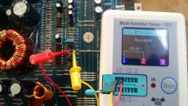
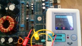
Also you'll see here that DP3 (zener diode) is testing as a 132.9 ohm resistor. But DP4 tests as a double diode.
I believe since the DP3 zener diode is also defective and could be the reason why the bank of IRF3205s go up in flames when I apply ~ 12V to the board.
Is this also correct thinking?
I believe since the DP3 zener diode is also defective and could be the reason why the bank of IRF3205s go up in flames when I apply ~ 12V to the board.
Is this also correct thinking?
Attachments
By using that particular device tester, its best you do an out of circuit test on the devices you suspect. my experience thats for a standalone devices under test and not incircuit.
You are reading the parallel diode/base-emitter. The one that doesn't read as a double, has an open driver transistor.
- Status
- Not open for further replies.