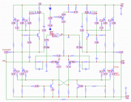
Sorry: Which one is the protection-transistor ? The mpsa 18 at the gain- or current source-mosfets or all of them ?
Best Regards
Best Regards
Q4 & Q9 on hifizen's schematic.Blitz said:Which one is the protection-transistor ?
/Hugo 🙂
OK, I made the assumption that you mean Q4 and Q9 in Hifizen's schematic. I removed them. No effect.
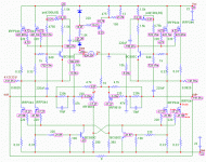
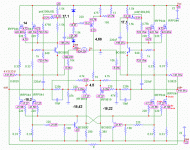
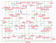
I simulated a working version with 20V, which I adjusted for 6mV offset. I reduced the voltage to +/- 10V to make it more realistic for your current setup. You can see the DC now is 2.43 V. The amp draws 6.41A.
I removed all references to part numbers to avoid confusion. Here you have all voltages and they shouldn't differ a lot from real life. Let me know, I can post a version with 20V or whatever you like. Currents and power dissipation are also possible.
/Hugo 🙂
I removed all references to part numbers to avoid confusion. Here you have all voltages and they shouldn't differ a lot from real life. Let me know, I can post a version with 20V or whatever you like. Currents and power dissipation are also possible.
/Hugo 🙂
Attachments
That is GREAT !
A 22V version would be helpful as this is what I use currently. As well it would be good to see the resistor values you used to ensure that I used the same.
Thanks a lot.
A 22V version would be helpful as this is what I use currently. As well it would be good to see the resistor values you used to ensure that I used the same.
Thanks a lot.
Nothing to thank 🙂 You gave us the high power thread; The least we can do is try to help you out now.
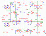
Here you go for the 22V version. Notice the theoretical offset of -141µV. Resistor values are added, part numbers not. Let's refer to Hifizen's schematic for that.
Note that values like feedback, input resistors and some others can differ from your version but that shouldn't influence the overall DC values too much.
/Hugo 🙂
Attachments
OK, here are some values I measured...I was not able to complete it, because the left side went completely to hell. I was impressed by the nice firework of the 5W-Wirewoundresistor I used as a source resistor - real flames etc after having it 4min continuesly on. Was this because it was still with protection transistors ? But why survived the other side without a problem ?
Attachments
OK, some assumptions:
Your measured values around the input diff pair and their current source are not important for the moment, they can differ according to the used components.
What catches the eye is the 14V at the gate of the left Aleph current source.
I tried a lot of things in the simulator with that current source. The only thing that gives 14V at the gate and the 17.1V is a wrongly connected BC550.
/Hugo 🙂
Attachments
Now for the currents. If your BC550 is indeed wrongly connected, the current draw doubles.
This perfectly explains why the whole setup keeps blowing. With a simulated 5.17A in normal condition, the current doubles to 10.6A. The left gain fet dissipates 109W, the current source fet 47.4. In normal condition this should be around 27.5W. Your source resistors hit almost the full 5W. Note that this is only an assumption but worth checking IMHO. Especially because the base of the BC550 is the middle pin, so collector and emitter can be switched easily.
Hope this helps. 😉
/Hugo – whishes Blitz a good night 😴
Good thought, but the BC550C are connected in the rigt way.
Let make some assumptions:
1. I made some errors initially like having the 044n not really isolated etc. (for sure)
2. I blew some stuff initially and still I have damaged components in the amp.
3. Some of the used resistors (0,125W) for the board have blown initially or are as well to weak for normal operations.
So, this raises two questions:
- Which parts are mostly in danger to be still defective ?
- What is the minimum required power spec for each resistor on the board ?
Best Regards
To be more concrete: What is the power over each resistor in your last simulation ? I guess then I might find the sick ones without de-soldering everything.
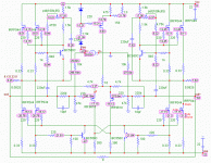
Here you go for the power dissipation of all components.
Normally 0.125W looks a little low to use as overall resistor.
I went for the 0.6W metal film types.
I'm sorry to say but if the damage is so big as you describe, probably all mosfets could be affected, apart from blown resistors.
If the BC550 is correctly wired, I can not think of something else for the moment. Maybe some EE guys can explain more in detail what could be the cause of that 14V at the gate.
I will post you a picture with all currents too.
/Hugo🙂
Attachments
Ok, next try: I have replaced most of the power mosfets as they have been destroyed last time. Well...I have still 14V at the collector of the upper BC550C. I guess the reason for that is because no current flows through R15/R32.
This should be an issues which can be solved. I guess reasons for this behavior could be (and please complete the list):
- The BC550 is dead: Just exchanged one of them, same reaction.
- The BC550C is wrongly connected. Checked this again with the Data Sheet in my hand. Connection should be right (so the transistor needs to be turn by 180 degree compare to a mpsa18)
- What else ? Could the 47,5K for R11 and R33 be to big as an initial value ? Need to check this.
- Any other ideas ?
Best Regards
Halleluja ! That did the job. I soldered a 4k7 resistor parallel to the 47K and now we are in business...4V as simulated...
Blitz said:- What else ? Could the 47,5K for R11 and R33 be to big as an initial value ? Need to check this.
I didn't notice that the 4.7K was 47K on Hifizen's schematic.
One thing still puzzle me.
1) How come the first half of the channel appeared to be ok.
You probably had a 47K there as well.
Anyway, very glad you made it; well, lets hope. 😉
/Hugo 🙂
- Status
- Not open for further replies.
- Home
- Amplifiers
- Pass Labs
- Help needed: Firing up the Aleph-X100
