I will fiddle with the gain knob on the signal generator. I had earlier adjusted it before the first picture was taken to just below flattening of the peaks of the wave (clipping?) but I can see why I should open it all the way for a test.

Yes ! I need glasses.The numbers in circles are the pins of the double triode not voltages ... grid is 0V , cathode 1.7V and so on , of course the clipping possibility is real .
To test 10 kHz squared... the effect of the volume in the input must be removed. your pot is 250k. If you do not set it to the maximum, it is able to filter high frequencies. The capacitor inside the 6sl7 and input pot canchang your test result.
To do a test for Voltage Gain, amplifier input to amplifier output:
Use a 1 kHz sine wave.
Set the amplifier volume to maximum.
Set the signal generator output voltage to minimum.
Connect the scope to the (loaded) amplifier output tap, and then turn the signal generator up, look at the sine wave, turn the generator up more until you see the sine wave just begin to clip, and turn it back a little until there is no more clipping (if the gain is low so that it never clips with maximum volts, that is OK too, but most generators have enough output volts to make the amplifier output clip).
Now measure the sine wave volts at the input, Vi.
Measure the sine wave volts a the output, Vo.
Vo/Vi = the amplifier gain.
"You should make things as simple as possible, but no simpler" Albert Einstein
Lots of steps above, each step is simple, simply follow them and you can not go wrong. You will know the full voltage gain of the amplifier.
For fun, your scope has Volts rms measurements. Set the generator output so the sine wave is just before / just below clipping.
Measure the amplifier output Volts rms.
(Vrms)squared / load Ohms
Suppose you connect these loads to the 4 Ohm tap . . .
Examples:
4 Vrms and 4 Ohm load = 4 Watt
4 Vrms and 8 Ohm load = 2 Watt
Using a sine wave of 4V peak (8V peak to peak) into 4 Ohms, (that is only 2.828Vrms), so it is 2 watts.
Using a square wave of 4V peak (8V peak to peak) into 4 Ohms, (that is 4Vrms), so that is 4 Watts.
Square waves of a specific peak to peak voltage, versus a sine wave of the same peak to peak voltage . . .
The power of the sine wave is double that of the sine wave power (square wave is 3 dB more power)
Last edited:
The gains in the amplifier, Post # 1 are:
6SL7 G = 56
6B4G = 3.2 (when the output transformer is loaded with 4 Ohms on the 4 Ohm tap)
2500 Ohms to 4 Ohms = 1/25 (when loaded with a 4 Ohm resistor on the 4 Ohm tap).
An 8 Ohm load on the 4 Ohm tap will give a little more gain on the 6B4G, about 3.6.
Total gain, volume full, is 56 x 3.2 x (1/25) = 7.2 (approximately). Possibly a little less, lets allow for a 1 dB insertion loss of the output transformer (0.89)
In that case, 7.2 x 0.89 = 6.4
If it is not close to 6.5 or 7, then the schematic is not correct for the parts values.
If the 4 Ohm tap is loaded with 8 Ohms, the gain will be about 7.3 or 7.8.
Make the measurements, and let me know if I am correct (or all washed up as an analyst).
So I would expect 7 overall gain
I also get the same value when I compare the steepness of the flanks. The trapezoid of the signal generator has the steepness of approx. 22V/ms. The amplifier output delivers approx. 150V/ms. Therefore the gain is approx. 150/22 = 6.8.
Last edited:
His "calculation" may be based on infinite bandwidth and also does not take the properties of this scope into account.
Of course, this is not an exact calculation. This way one could at least estimate the grand order. In any case, the gain is clearly > 1.5.
Depends. If you look at it on the source/generator, doubling the amplitude of the output signal there's a good chance that the steepness also gets close to doubling.
If you look at the output of an amp while doubling the input signal level, you come up short, because the amp doesn't have infinite bandwidth.
So you always lose some higher harmonics of the input signal which messes up the picture.
It all depends on the linear distortion of the amp and the characteristics of the signal.
Jan
Question?
Do you want to know the amplifier gain from 100Hz to 10kHz?
Then use sine waves of 100Hz, 1kHz, and 10kHz.
Or are you wanting to check the amplifier gain from DC to light?
If not, then why use a triangle or a square wave to check gain?
Leave out the low frequency effects, leave out the high frequency effects, and leave out the slew rate effects . . . instead use a sine wave to check the amplifier gain.
Just my $0.02 worth.
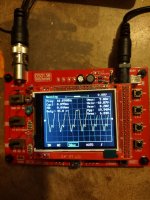
I'm just a caveman throwing a wrench at this thang. Sounded good before I put a scope on it, still sounds good. 10k square wave looks a lot better than some of the kit amps I've built so far.

6B4G + 6SL7

10kHz sq wave

EL84 kit amp

10kHz sq wave


6B4G + 6SL7
10kHz sq wave
EL84 kit amp
10kHz sq wave
Attachments
Those are very sick waveforms , that amplifier must be redone ... 🙂
And is not normal at all for waveforms to be so asymmetrical between top to bottom , even the "good" ones . If the input has 50% duty cycle the output should be the same .
And is not normal at all for waveforms to be so asymmetrical between top to bottom , even the "good" ones . If the input has 50% duty cycle the output should be the same .
- Home
- Amplifiers
- Tubes / Valves
- Help me understand? 10kHz square wave thru my SE amp