Ok. Have a good night.Ok. By now, leave the audio sector alone. Wire the screen and plate of the RF output. Use by moment a 100K @ 1W (or similar: 120K, 82K, 2 x 47K etc.) resistor for the 802's screen. It may be excessive, but as it will be the first time you manipulate a tuned amplifier, it is safe for you and the tube. Still no test it with DC because I need to say how to adjust it. Remeber wiring the milliammeter into the RF amplifier section. Unless you find another source of data more reliable than me 🤔 🙄.
Now I'll go to bed. We had 34°C today and I suffer a lot the hot weather. I prefeer 16 to 18°C for comfort.

Understood.If the PA has no pewer supply wiring, it's ok to find negative voltages where ot is supposed to be positive. Electrons boiling from the cathode strikes plate and screen accumulating in those electrodes.
I want to check just to make sure. You ment to wire resistor across the plate and screen, right? And plate goes directly to coil, no resistor in series?
OK. Ready to hook the amplifier into the power supply through modulating choke?.
Momentarily take off modulating tube from its socket.
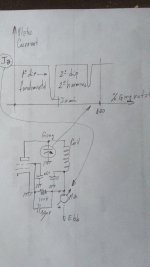
Below is rougly depicted the amplifier behavior. With the oscillator runing, give power supply to the final stage. The current in the mA will show surely a large current. Thus, start to rorate the tank's gang slowly from the plates totally closed (maximum capacity condition). If all is OK, there must be a point in the angle of rotation that the current starts to drop. Then it will increse again as you continue rotating it. The dip in the plate current means the plate circuit is tuned into resonance with grid signal and is what we are interested to get. Search with care the minimum of plate current. It may happen that if you continue opening the gang, to found a second dip of lower depht. This point is the second resonance an the amplifier now is a frequency doubler, that is the amplifier doubles the frequency on its grid. In audio, it is undesirable (harmonic generation), but in RF ot is sometimes desired and wanted. Also it may create a third harmonic and we have a frequency tripler. With the constants we have, it is possible to find the 2nd harmonic but rarely the 3rd.
Once the dip in the plate current is found, move slightly the plastic gang in the oscillator. You surely will found the dip is still more depth. Iterate 3 or 4 times readjusting both gangs until the dip is no longuer upgradeable. This is the proper tunning without load of the amplifier. If you have the receiver to be used as monitor, you must ear a depth, and loud clean signal into it.
Momentarily take off modulating tube from its socket.
Below is rougly depicted the amplifier behavior. With the oscillator runing, give power supply to the final stage. The current in the mA will show surely a large current. Thus, start to rorate the tank's gang slowly from the plates totally closed (maximum capacity condition). If all is OK, there must be a point in the angle of rotation that the current starts to drop. Then it will increse again as you continue rotating it. The dip in the plate current means the plate circuit is tuned into resonance with grid signal and is what we are interested to get. Search with care the minimum of plate current. It may happen that if you continue opening the gang, to found a second dip of lower depht. This point is the second resonance an the amplifier now is a frequency doubler, that is the amplifier doubles the frequency on its grid. In audio, it is undesirable (harmonic generation), but in RF ot is sometimes desired and wanted. Also it may create a third harmonic and we have a frequency tripler. With the constants we have, it is possible to find the 2nd harmonic but rarely the 3rd.
Once the dip in the plate current is found, move slightly the plastic gang in the oscillator. You surely will found the dip is still more depth. Iterate 3 or 4 times readjusting both gangs until the dip is no longuer upgradeable. This is the proper tunning without load of the amplifier. If you have the receiver to be used as monitor, you must ear a depth, and loud clean signal into it.
Attachments
No. Screen resistor goes to the cold side of the plate tank, for DC are the same but no for RF voltages. The hot side is only composed by bottom wire of the coil, the stator of the variable capacitor and pentode's plate. No more things there.I want to check just to make sure. You ment to wire resistor across the plate and screen, right? And plate goes directly to coil, no resistor in series?
Directly to the tank, bypassing the .01 capacitor?No. Screen resistor goes to the cold side of the plate tank, for DC are the same but no for RF voltages. The hot side is only composed by bottom wire of the coil, the stator of the variable capacitor and pentode's plate. No more things there.
Ok. So I also add 10uF bipolar and .01 to the screen?Take a view of the pic at post #306.
I had found the dip, there is only one. I can clearly hear it on the radio, buzz goes away and some static remains.Yes. The screen bypass must be there. The 10uF may wait.
Bit of solder has jumped onto the gang and I didn't see it, unpleasant experience. Well I had my hand on the switch and switched off instantly. Thankfully it works.
Current is a bit bellow 10mA.
It lights up a herz loop 🙂
Last edited:
Wonderfull. Now its time to modulate it. 10mA for such a valve is okay. Hook on the '86 and attach the "mic" or "mike" (microphone) to the '86 triode's grid. Start the pot (modulation index control) from zero and increase until the desired level. Maximum m (modulation index) is 100% for an undistorted AM transmission (theoretically). Thus increase pot until the TX sounds distorted in the receiver. Once more, retune the amplifier. Or the coupling to receiver make them to oscillate (Larsen effect).
When attaching a load to any tuned amplifier, it will detune. In a tuned circuit, inductive and capacitive reactances are equal and (logically) on opposite phase. As you are coupling inductance (the loop itself), resistance (the bulb) and sometimes capacity (a slightly mistuned antenna), it will run out of proper tuning increasing L or C depending on load reactance. So you must readjust tank setting almost every time you make a change in the operating conditions. This also is normal too. Usually oscillator tank isn't necessary to readjust because you are using only one fixed frequency Xtal defined.
You will also see variations of bright of the bulb at the audio level and a small variation in plate current. Excesivelly larger needle variations means amplifier being unlinear, that's overmodulated [m>100% or m>1], or misadjust in the RF tuned amplifier.
It works. I had tryed with music and the mike. Herz loop with it's bulb helps alot to indicate if big gang is adjusted right.Wonderfull. Now its time to modulate it. 10mA for such a valve is okay. Hook on the '86 and attach the "mic" or "mike" (microphone) to the '86 triode's grid. Start the pot (modulation index control) from zero and increase until the desired level. Maximum m (modulation index) is 100% for an undistorted AM transmission (theoretically). Thus increase pot until the TX sounds distorted in the receiver. Once more, retune the amplifier. Or the coupling to receiver make them to oscillate (Larsen effect).
When attaching a load to any tuned amplifier, it will detune. In a tuned circuit, inductive and capacitive reactances are equal and (logically) on opposite phase. As you are coupling inductance (the loop itself), resistance (the bulb) and sometimes capacity (a slightly mistuned antenna), it will run out of proper tuning increasing L or C depending on load reactance. So you must readjust tank setting almost every time you make a change in the operating conditions. This also is normal too. Usually oscillator tank isn't necessary to readjust because you are using only one fixed frequency Xtal defined.
You will also see variations of bright of the bulb at the audio level and a small variation in plate current. Excesivelly larger needle variations means amplifier being unlinear, that's overmodulated [m>100% or m>1], or misadjust in the RF tuned amplifier.
However I have a big problem. It's the buzzing. It is much louder than the sound. Shorting signal input to gnd doesn't help and I can hear different buzz when touching input path... This makes me beleive it's not the input. Once I tune the big gang to the right position, buzz comes much louder.
EDIT:
Buzz was actualy caused by phone charger just being plugged into the cord... It' much better now. I need to filter the psu.
SECOND EDIT:
Buzz returned as I wired gnd for signal path, looks like that ground wires are picking up alot of buzz. If I hold my hand close to one of the gangs, buzz is reduced for about 90%.
Mike would require preamp, music is acuatlly pretty listenable at 3/4 of the volume and bass turned all the way up / high all the way low. Will play with eq on the phone to see if this could be altered with tone control or filter at the input.
Last edited:
It may happen that the audio amp picks up part of the RF field and turns it into unlinear region or into oscillations.
The only way to calm it is by proper design of the chassis, layout and shielding.
Thus if you want to continue, you must search for a metallic chassis, proper grounding and shielding of the stages.
Vintage ham transmitters had the RF section in a own chassis on top of a rack, audio at middle and power supply at bottom.
In the way you had done it, it's quite satisfactory. Enjoy it as is.
Now you have a small AM transmitter with the all parts as a proffessional one has: a master oscillator, and a power amplifier. A modulator consisting of a preamplifier and a power modulator. And a power supply. All it at small scale, but all parts as a big AM broadcasting.
I like it alot. I didn't expect that music would be so listenable. But it is. I will start with shortening audio path & heather wires.It may happen that the audio amp picks up part of the RF field and turns it into unlinear region or into oscillations.
The only way to calm it is by proper design of the chassis, layout and shielding.
Thus if you want to continue, you must search for a metallic chassis, proper grounding and shielding of the stages.
Vintage ham transmitters had the RF section in a own chassis on top of a rack, audio at middle and power supply at bottom.
In the way you had done it, it's quite satisfactory. Enjoy it as is.
Now you have a small AM transmitter with the all parts as a proffessional one has: a master oscillator, and a power amplifier. A modulator consisting of a preamplifier and a power modulator. And a power supply. All it at small scale, but all parts as a big AM broadcasting.
As I spent quite some time with working on amplifiers, I know where I want the amp to be. Away from the radio circuit and away from the PSU, but as wiring must be short I am thinking of putting it to the right of the big gang and make a metal plate in the shape of L, connect it to the ground, to keep the radio and the trafo "isolated" from the modulator.
Does it sound like a good plan to you, or would metal plate pickup even more interference as ground wiring seems to pick up a lot?
Right now modulator is far left, but that calls for long wiring...

I almost forgot... The 10uF bipolar cap. Do I wire it in?
It may be a toy, but it opened my way to RF and I learned a lot. I like the device and whole concept of RF. It's something new to me.Don't forget that it's a toy.
Place the cap across dropping resistor and the 802's data sheet says the maximum plate current is 15mA. So you can reduce the screen droping resitor until the milliammeter say 18/20mA because of the sum of screen and current plate.
I will thinker with it to get it working best without too much of modifications, minimizing the buzz is my first task and will I will also play with the screen dropping resistor.
My life calls for learning to take the tests and get the MOT license, to get my salary bit higher. So I will need to spend some time to learn about all the laws, specs, etc ... work is work.
With that said, I will finish this transmitter and when I pass the MOT tests I'm looking forward to explore the RF world. I will start with simple transmitters with ICs. There is alot of schematics online. Will also look into the regen receiver with tube... I see alot of low voltage builds online.
Thank you Osvaldo for helping me with the project and making this possible for me.
If you will need help with cars or need a companion, you have my email.
No, thankyou. In fact I hate cars. They are a waste of energy. Think that you are putting into movement a mass of 1~2 tons and a person only wheights 100K rounding numbers. Thus only 5~10% of the energy is used to move payload. Under this, it is know that in an internal combustion engine, the thermal efficiency is under 20% theoretically. Take out the power lost in pumps, transmission gearing, alternator... So only 3 or 4% of the combustible is used to move you. I preffer bike for short distances or bus for longuer ones. Railroad is not close to where I live.
Respect to your tx, there may be an ultimate step you can do. Reducing a bit the voltage dropping resistor about triode oscillator, we can take a little more power from it to drive the 802's pentode. It will also give a little more power. Thus we can do that the 802 drive the PL tube you had and use it to double the frequency and obtain increased power from them. If you want to steep it, you will need a smal bulb like those in microwave ovens (10/15W), another big gang and a new plastic tube for the final tank. This will add some power and introduce the frequency multiplier concept that is inexistent in the digital world: there you have counter and frequency dividers, not multiplers. There isn't need to do it right now, lets do it when you wish.
Respect to your tx, there may be an ultimate step you can do. Reducing a bit the voltage dropping resistor about triode oscillator, we can take a little more power from it to drive the 802's pentode. It will also give a little more power. Thus we can do that the 802 drive the PL tube you had and use it to double the frequency and obtain increased power from them. If you want to steep it, you will need a smal bulb like those in microwave ovens (10/15W), another big gang and a new plastic tube for the final tank. This will add some power and introduce the frequency multiplier concept that is inexistent in the digital world: there you have counter and frequency dividers, not multiplers. There isn't need to do it right now, lets do it when you wish.
Last edited:
Well, when you put it that way cars really don't make much sense. But to me it is a pleasure to drive a drivers car & enjoy the sound of an engine. Makes me calm, no mather how fustrated I was when I sitted into it.No, thankyou. In fact I hate cars. They are a waste of energy. Think that you are putting into movement a mass of 1~2 tons and a person only wheights 100K rounding numbers. Thus only 5~10% of the energy is used to move payload. Under this, it is know that in an internal combustion engine, the thermal efficiency is under 20% theoretically. Take out the power lost in pumps, transmission gearing, alternator... So only 3 or 4% of the combustible is used to move you. I preffer bike for short distances or bus for longuer ones. Railroad is not close to where I live.
Respect to your tx, there may be an ultimate step you can do. Reducing a bit the voltage dropping resistor about triode oscillator, we can take a little more power from it to drive the 802's pentode. It will also give a little more power. Thus we can do that the 802 drive the PL tube you had and use it to double the frequency and obtain increased power from them. If you want to steep it, you will need a smal bulb like those in microwave ovens (10/15W), another big gang and a new plastic tube for the final tank. This will add some power and introduce the frequency multiplier concept that is inexistent in the digital world: there you have counter and frequency dividers, not multiplers. There isn't need to do it right now, lets do it when you wish.
Unfurnately as much as I want to take it a step further with PL, I really need to study for the tests. It works like that: company applies you and you have to go. If you fail you just loose the money for the test and drive.
I would like to do it when I will finish that test.
But I would like to reduce the triode's dropping resistor.
I didn't lower the pentode's screen dropping resistor yet, still have to do that.
I had wired in the 10uF bipolar and light on the herz loop doesn't shine as bright, but it reduced the buzz.
I had found out that I can alter the frequency quite a lot... my starting point was 7.3mhz, but I can lower it to about 6.7mhz... god knows for how much higher it can go, but my receiver wont do above 7,4mhz. At the higher frequency that my reciever can't hande I can get the herz loop bulb to shine much brighter.
Also is the herz loop a good test for power output? I'm asking because sometimes bulb is not lighting at all, but I can get better sound from the radio.
- Home
- Amplifiers
- Tubes / Valves
- Help me put these tubes into good use... I need a project