As I mentioned above, I have doubts the thermistor is the basic issue but there is a very small chance it could be. You need to understand how transformers behave when subject to a rapidly fluctuating input voltage to understand why that could blow a fuse but it can.Since I have them off the board I will replace them but I am thinking this is not the issue with it blowing fuses. The board looks good too.
What do you guys think?
All you can do is try it... it has two choices 🙂 It will either work or it will blow again.
Also and just to cover all bases... check the wall plug and socket are good (no loose connections) and the fuse holder is tight. Any intermittent connection in the mains feed can cause the fuse to blow.
Yes, I will definitely replace the thermistors and try it again.
The fuse holder and the power cord socket seem to be tight. The wall outlet isn't the issue because the 1st time it blew it was in my rack and my testing is being done in my workshop on a totally different circuit. Power cord has already been eliminated.
You mentioned in an earlier post that something downstream might be causing this - the next component is the very large toroidal transformer and from there it goes to the power caps.
To me, it almost sounds like a short somewhere but I may not be skilled enough to find it by myself. May wind up taking it to an expert.
I think it's clear that the Thermistors are not your real problem. They simply suffer when the amp draws too much current, as if the inrush never stops. I don't get the impression that you are familiar with amplifier failures. Shorted power transistors are a start but because they are directly connected to driver transistors etc, repairs are complicated. When you are familiar with all the stages and bias circuits in an amplifier, then you can fix them. You start with testing all the parts in the amp with an ohm meter etc, replacing the failed parts, and then bring the amp up slowly with a current limiting resistor/ lamp until it powers up with the normal idle current. Then you run a test signal and scope the results, first unloaded and then into dummy load, looking for premature distortion and instability...

You mentioned in an earlier post that something downstream might be causing this - the next component is the very large toroidal transformer and from there it goes to the power caps.
To me, it almost sounds like a short somewhere but I may not be skilled enough to find it by myself. May wind up taking it to an expert.
Its possible of course although it doesn't sound like a normal failure as usually once something goes short circuit it stays short circuit.
With such a large amp and transformer and reservoir caps then if something was going short across a rail it would cause quite a bang as there is so much energy involved... and I take it that doesn't happen.
Another possible suspect could even be the mains switch. All those things are easy to prove as long as the fault remains reproducible, The switch can be shorted out as a test.
By "mains switch" do you mean the on/off switch on the amp? I already tried bypassing it and it still blew a fuse. That was what I first suspected the problem to be due to it not wanting to come on sometimes.Its possible of course although it doesn't sound like a normal failure as usually once something goes short circuit it stays short circuit.
With such a large amp and transformer and reservoir caps then if something was going short across a rail it would cause quite a bang as there is so much energy involved... and I take it that doesn't happen.
Another possible suspect could even be the mains switch. All those things are easy to prove as long as the fault remains reproducible, The switch can be shorted out as a test.
I couldn't locate anyone selling that exact spec. I did find this one at mouser - the amps and ohms match, it is just a smaller diameter physical size.It looks like a NTC thermistor, a quick google with UEI 20SP005 and I found the attached datasheet, not the same manufacturer but the specs are the same.
Seems to be 5 Ohm at 7amps.
Suitable substitute?
Thanks.
Entirely likely that it could be something a lot more serious and involved than what I am currently looking at. I am eliminating the easy DIY stuff first; If I can't fix it with the simple and obvious things, I will take it to a repair shop. It is an old amp but it is very clean on the inside and it was sold through an estate sale. It has been working fine but I am starting to suspect that the previous owner had this intermittent issue and just put it away in a closet for years and the family put it and all his other gear up for sale not knowing there was a problem. It has been working fine for me for about 5 months now.I think it's clear that the Thermistors are not your real problem. They simply suffer when the amp draws too much current, as if the inrush never stops. I don't get the impression that you are familiar with amplifier failures. Shorted power transistors are a start but because they are directly connected to driver transistors etc, repairs are complicated. When you are familiar with all the stages and bias circuits in an amplifier, then you can fix them. You start with testing all the parts in the amp with an ohm meter etc, replacing the failed parts, and then bring the amp up slowly with a current limiting resistor/ lamp until it powers up with the normal idle current. Then you run a test signal and scope the results, first unloaded and then into dummy load, looking for premature distortion and instability...
I couldn't locate anyone selling that exact spec. I did find this one at mouser - the amps and ohms match, it is just a smaller diameter physical size.
Suitable substitute?
Its difficult to say without the datasheet of the original thermistor or whether the thermistors are switched out of circuit after switch-on.
There's more to the resistance and current rating. We also need to know the energy in joules and the time constant.
Link - Selecting a NTC thermistor at the Ametherm Website.
It is always in the circuit - it is on the main load wire from the power input at the back of the unit so there is no way for it to be switched off or out of the circuit. That small circuit board doesn't connect to anything - It looks to be just there as a means of joining all the thermistors and the wiring.Its difficult to say without the datasheet of the original thermistor or whether the thermistors are switched out of circuit after switch-on.
There's more to the resistance and current rating. We also need to know the energy in joules and the time constant.
Link - Selecting a NTC thermistor at the Ametherm Website.
Not sure how I would find the energy and time constant - this amp was made in 1990s by Parasound. It is a 2200II model.
I did yes.By "mains switch" do you mean the on/off switch on the amp?
Does the amp blow the fuse each and every time or is it very intermittent?
For test purposes only you could use a bulb (something like a high wattage mains filament bulb, perhaps even a mains halogen 300 or 500 watt type) wired in place of the fuse. You would also link the thermistors out.
If a fault occurs in the amp then the bulb should light limiting current. The bulb trick works because of the non linear relationship of filament vs temperature. When cold a high wattage halogen will have a resistance of just a few ohms, just like your thermistors. In fact it behaves in a similar way.
I'll not edit the above... instead of linking the fuse out, just fit the bulb in place of the thermistors as a test. Same setup, easier and it leaves the fuse in circuit.
I did yes.
Does the amp blow the fuse each and every time or is it very intermittent?
For test purposes only you could use a bulb (something like a high wattage mains filament bulb, perhaps even a mains halogen 300 or 500 watt type) wired in place of the fuse. You would also link the thermistors out.
If a fault occurs in the amp then the bulb should light limiting current. The bulb trick works because of the non linear relationship of filament vs temperature. When cold a high wattage halogen will have a resistance of just a few ohms, just like your thermistors. In fact it behaves in a similar way.
It uses ceramic fuses and I only had 2 of them on-hand but it blew both of them, 3 total now: the first time in my rack and the other 2 times on my workbench. Not intermittent - each time I turned it on. I bought more fuses but once I saw that thermistor smoking I didn't try any more.I'll not edit the above... instead of linking the fuse out, just fit the bulb in place of the thermistors as a test. Same setup, easier and it leaves the fuse in circuit.
I have a fuse holder so I may use your light bulb method and wire it in line with my fuse holder and bypass everything up to the transformer.
Will let you know results.
Thanks.
No, not something that I know how to do. I am trying to eliminate the basics before handing off to a repair shop.Did you check the rest of the power supply for shorted rectifiers or shorted filter caps?
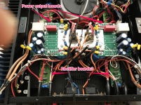
There are a lot of rectifiers - right? Looks like 2 boards, 1 board for each channel. If you mean these rectifiers, then there are at least 10-12 per channel. Each of these boards that hold the rectifiers is connected to both the main input board and the power supply boards. See pics. Note that I have removed the main input board - it goes in the area beside the output boards.
Attachments
See what it does with the bulb because you can then attempt to measure voltages on the secondary even if the bulb does light brightly.
The rectifiers are those 4 legged rectangular packages. You see you can undo the leads from the transformer to the rectifier as a further test.
What is this? It looks like a piece of coax cable that has been chopped 😀

The rectifiers are those 4 legged rectangular packages. You see you can undo the leads from the transformer to the rectifier as a further test.
What is this? It looks like a piece of coax cable that has been chopped 😀
That is the load wire going from the fuse to the thermistor board. I had to cut it to get at the thermistor board - I will resolder it back to the thermistor board when I get the new thermistors resoldered. (I was wondering if anyone would notice that wire - good eye. 😉)
It did occur to me that the rectifiers he was referring to were the bridge rectifiers. I can easily disconnect them as you note - another thing to check off on my list.
Thanks.
OK 🙂
One step at a time. Get a suitable bulb wired in series with the mains and then you can look further at what is going on.
One step at a time. Get a suitable bulb wired in series with the mains and then you can look further at what is going on.
- Home
- Amplifiers
- Solid State
- Help Identifying MOV