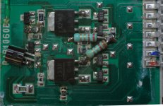
The zener doesn't have direct connection to pin 11, 8 and the fet. The component in question does and looking at the schematic identifies it as the npn. I found another picture of the module on the web where this component has PS marking vs the PR on mine. 2SD814 Datasheet shows both PR and PS markings in line with hFe ranking. I'm fairly certain that its the correct one.
Hey Rick,
Professional considerations do matter, but put them into context. That is what I tried to do. That viewpoint isn't always wrong you know.
I think it is valuable to bring out concerns in order to assess what you are doing. I do hope the repair is successful, don't get me wrong. If the repair was hopeless I would have said that, but I didn't.
A bit late at the party but in any case my repair was. In my case not only the driver transistor had gone phut, the source resistors had bitten the dust as well. Fortunately the MOSFETs were OK.I do hope the repair is successful

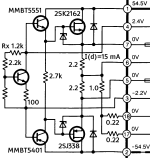
As I did not have the SOT23 SMD version of the 2N5401 (MMBT5401) I used the TO-92 version. Also made a schematic with the component values:

Very annoyingly the SE-A909 still doesn't work because the SVI powerslab goes into protect at only half a watt...
Hi Regenpak,
Have a look at the emitter (source) resistors, normally low resistance like 0R22 or similar. Overcurrent normally is tripped by the voltage across those resistors exceeding a set level. It is also possible the over-current detect transistor is leaky, or another resistor has gone open or high in value.
What model amplifier did you say this was?
-Chris
Technics SE-A909. The source resistors are high at 2.2 ohm (you actually can see these values printed on them in my pic above). This is a concept devised by Matsushita called Class AA that uses two amplifiers in a bridge configuration. Exactly what the problem was the Japanese engineers wanted to solve is a mystery but the idea is that the MOSFET powerslab amplifies the voltage part of the signal and the SVI powerslab the current. Hence the high value of the source resistors. Whatever the case, the SVI goes into protect after three seconds and I don't understand why. The SVI3205B contains a lot of additional circuitry amongst which a protect chip akin the TA7317P. The protect signal from the SVI goes to the speaker relays.What model amplifier did you say this was?
Hi Regenpak,
Thanks for that. I'll try and look it up next week. I'm gone for the weekend.
2R2 is stupid high, and yes, Japanese engineers do the most unfathomable things some times. You lose too much power in a 2R2 resistor, and then you have to make it very high power. For that reason alone, are you certain there are no lower value resistors somewhere? This is just physics.
Three seconds does sound like a time out, or time constant. Your DC offsets are okay? (I think you must have checked).
-Chris
Not only that, I checked the craziest parameters. Like the actual current drawn from the output over a 1R resistor into 8R dummyload:Your DC offsets are okay? (I think you must have checked)
Or the current drawn from the positive rail:
Also across a 1R resistor. Fully consistent with an 8R load and 8 Vpp (1 W) into this load. You see the ripple of the 50 Hz mains and the peaks of my sine wave test signal of 500 Hz. Exact same thing on the negative rail. I went along all the pins to look for a sign of protect activity but found none. Zilch. Nada. Niente. Nakko.
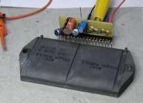
So I took the powerslab out (it happens to be an SVI3205C clone, no idea what's the difference, documentation is next to non-existent) and put it into a custom test jig:

Flawless operation! This is the old unit that indeed is borked. Both sections rail. Forgot which one. Doesn't matter.
I am stumped. I've ran out of inspiration on how to proceed to get this amp going. This is a satan's amp. Maybe I should try an exorcist.
In any case, thanx for looking over my shoulder...
Hi Regenpak,
Just a thought. Check that Q451 (Q452) are3 working properly. These should be constant current sources. They work with Q401 (Q402) so they work in in class A. The AN7062N normally does not require anything like IC502 to begin with. It looks like IC502 only provides a little extra current gain to isolate IC401 (AN7062N) from load variations. Not really a huge concern. It may also allow the AN7062N to work from a higher supply voltage. I'd have to look that up to be certain.
There is no overcurrent detection built into the RSN6000B. Sense resistors only. A TA7317P is like IC501 (SVI3205B). So on the RSN6000B, look at pins 13 (6) and 12, 17, 18 (5, 15, 16). Pins 13 and 6 are your signal out pins. I'd have to assemble the schematic and trace back to sort out exactly what they are doing. I can see it is much more complicated than it really needs to be. Also look at the signal inputs on the SVI3205B to see which of the fault detection circuits is tripping the protection.
This is more difficult and frustrating to troubleshot due to the excessive complexity. One thing to look at are the electrolytic caps in the protection areas. If one is basically open, a signal will look like DC offset an trip that function.
-Chris
Because the documentation is incomplete it is hard to figure out. The idea is that RSN does the voltage amplification and the SVI delivers the current. How exactly the output of the SVI is routed back to the RSN (that bridge idea) is unclear. The SVI acts as an error amp to balance the bridge. Or something.I'd have to assemble the schematic and trace back to sort out exactly what they are doing.
Right now I've tossed this amp aside. I still have the SVI in my test jig and will test it at the amp's PSU. I expect flawless operation like I have now on lower voltage. Your suggestion to look into the DC offset is a good one. I never checked it because it is not obvious but the constant 3 s delay is an indication it could be the cause of my issue.
I will report back once I've tried the next two steps. Test the SVI in my test jig on amp power and put it back in and check the DC offset. Right now I have no idea where that would come from. So far I tested both channels at the same time but I will test one at a time the next time. So three steps... There are no electrolytics because the protect circuit is inside the SVI. Which only had SMD ceramic caps.
Thanx for thinking along!
Tjerk
Check C507 and C508. They have to filter out the AC signal in order to get a DC average which they detect for DC offset. If the cap is open, an AC signal will look like a detected DC offset fault.
C508 is the relay timing C at switch on. I did not detect any DC offset related activity at C507 but I will replace it in any case. Maybe it is the kill C at switch off (AC DET).Check C507 and C508
The AC detech would prevent the unit from turning on, or delay start-up. It could also shut it down randomly as the voltage varied.
No, somewhere they have to rectify the output signal for each channel, then detect the average value for a DC bias. That is the standard way all these offset protectors work, and it is also "by definition". If you don't average the output, it will detect peak values (ie music) and trip into protection. That might explain what is happening here.
Pins 12 and 13, then pins 15 and 16 for each channel are for over-current and maybe DC also. Look at capacitors C501 through C504.
This isn't drawn very nicely, and of course they had to get creative with protection. The needed circuits are simple, but they just had to make them very involved. Yamaha does this as well. It's as though Japanese engineers just have to show off, and these are the places where you get weird faults.
Yamaha varactor tuners are a real nightmare to align, just as some early Kenwood that use tuning caps also. No reason for any of this. (I'm fighting through alignment of a Yamaha tuner that someone messed with). So take heart, you aren't "not getting it", it's a stupid circuit.
I wholeheartedly concur!it's a stupid circuit
BTW- which Yamaha are you fighting with? I am good with tuners, on another forum I'm also known as Dr. F.M. Tuner.
Tjerk
Yamaha R-700. Someone played with the alignment so it didn't even lock on stations. No manual tuning.
The procedure is pretty stupid, making jigs and the alignment can take a while. Once you're done it doesn't even perform well. Some steps are incorrect as well. I have a ton of equipment for doing tuner alignments and am well known for that work. I tend to get everything someone else has tried and messed up. "panicking technician" syndrome makes life difficult sometimes.
I use a Revox B261, the best tuner ever! I was authorized warranty for Revox, and Yamaha plus a bunch more. Most of my stuff is HP, Agilent and Keysight. I also have some classic generators like an SMG1 and Sound Tech 1000A. I probably have 9 or 10 generators for FM work, plus spectrum analyzers and other things. I have a jig I use to match and test ceramic filters.
I get really annoyed with complicated alignments with poor performance. A real waste of time if you ask me! The Revox is involved, but the results are more than worthwhile!
I deduce from the low Vgs and low gm that those are lateral mosfets.A bit late at the party but in any case my repair was. In my case not only the driver transistor had gone phut, the source resistors had bitten the dust as well. Fortunately the MOSFETs were OK.
View attachment 1184036
As I did not have the SOT23 SMD version of the 2N5401 (MMBT5401) I used the TO-92 version. Also made a schematic with the component values:
View attachment 1184037
Very annoyingly the SE-A909 still doesn't work because the SVI powerslab goes into protect at only half a watt...
With 50V rails, the drain currents cannot exceed 100mA or so or they will cook.
This is a very strange module, more of a buffer
Hi David,
Yes, it is just a buffer between the signal amp section and output section.
Really stupid. I think it is more intended to make the unit unrepairable.
Yes, it is just a buffer between the signal amp section and output section.
Really stupid. I think it is more intended to make the unit unrepairable.
Not sure if the MOSFETs in the RSN module are laterals. Something funky in between verticals.Really stupid. I think it is more intended to make the unit unrepairable.
As for the R-700, it has a bog standard frontend and ditto ratio detector. Did not delve into the remainder because as you say it is insanely complex. I feel your pain.
As for the Revox, I happen to own its predecessor, the A720 preceiver. Also a great piece of equipment! The evolution to the B261 nicely shows.
Still no courage to tackle the Technics though...
Tjerk
- Home
- Amplifiers
- Solid State
- Help identify replacement SMD transistor