lol!
yes, the FM tuner pak and detector are standard. However the controller IC interferes with normal methods and techniques. An excruciating experience! I know what needs to be done, but can't get it into the modes I need it to be in.
Yes, those were great receivers. Revox knew how to do some things very well. The later products (B251, B242) had serious design errors ranging from foil too thin, cheap PCB and thin traces and pads. Also components were allowed to run far too hot. Put that all together and you have products with problems that aren't fun to service. The B242 has adjacent pads 200VDC apart!!! Guess what happens? Yup, it arcs and burns the PCB. Lots of broken solder connections as well. The B251 will have cooked transistors and broken traces. You have to install larger transistors with heat sinks. Of course the PCB doesn't deal with that well either.
The B261 uses IF coils with modern electronics. Fantastic combination and the amazing performance shows. There is a lot to align, but it is well worthwhile.
The Technics isn't that bad once you figure it out. Stupid, frustrating - yes. I'll watch and try to make intelligent suggestions.
We're getting a bit off-topic here but what the heck... The A720 IF filter is nearly identical to the B261's. Bessel response so nicely phase linear. To get a sharp-ish response the Swiss needed no less than eight sections. I did some experiments based on this filter but found that the Q of the coils is critical in getting good results. Standard TOKO coils destroy performance. Revox' coils are very good and it shows.The B261 uses IF coils with modern electronics.
SMD is great technology if soldered by someone or preferably wave soldered. I have a tough time seeing the values on the big ones.
That being said my next amp will use more SMD as it is great tech.
That being said my next amp will use more SMD as it is great tech.
Hi Regenpak,
You're right. I agree with what you said as well.
Hi stocktrader,
It is, provided the running temperature and voltages are not too high. I've worked with it for decades. For prototyping, I'll take through hole any day.
You're right. I agree with what you said as well.
Hi stocktrader,
It is, provided the running temperature and voltages are not too high. I've worked with it for decades. For prototyping, I'll take through hole any day.
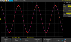
Got the courage to pluck this satan's amp out of its corner and give it another go. I used it to power the powerslab in my test jig at full voltage and as expected it will not go into protect even at clipping. So I put it back into the 909 using the silpads (the white goo is too yucky to even contemplate) I used with my test jig. Which worked very well. But all the same, just slightly over 1 W on both channels at engaging the speaker relays it conks out in 3 s:

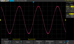
in protect:

You can see the amplitude is slightly less in protect because of the resistance between the powerslab output and the feedback point to the AN7062 (R407). The DC offset is a minimal 28 mV, way too low to trigger the DC protect circuit. Why it gets triggered anyway as soon as I connect a load to the speaker terminals is a total mystery. I'm even thinking of kludging together a TA7318-based protection circuit and use that instead. I've run out of inspiration to try to find the cause of this satanic behavior. I scoped every pin on the powerslab and they all behave nominal. As far as can be gleaned from the minimal documentation. As in: non-existent. So, frustrating as it is I'm afraid I have to admit defeat and go with the protect kludge. I will refuse to take in any future Technics repair. I now hate the stuff with a vengeance...

in protect:

You can see the amplitude is slightly less in protect because of the resistance between the powerslab output and the feedback point to the AN7062 (R407). The DC offset is a minimal 28 mV, way too low to trigger the DC protect circuit. Why it gets triggered anyway as soon as I connect a load to the speaker terminals is a total mystery. I'm even thinking of kludging together a TA7318-based protection circuit and use that instead. I've run out of inspiration to try to find the cause of this satanic behavior. I scoped every pin on the powerslab and they all behave nominal. As far as can be gleaned from the minimal documentation. As in: non-existent. So, frustrating as it is I'm afraid I have to admit defeat and go with the protect kludge. I will refuse to take in any future Technics repair. I now hate the stuff with a vengeance...
Hi Regenpak,
So you're saying (to be clear), you can run up to "x" voltage without tripping protection unless you load it, that's what I understand. Can you run the output up to 10 Vrms without load and have it stay in normal running mode?
Check the current sense resistors in the output chip or circuit. They may appear to be undamaged. It is possible no fault exists in that circuit.
If this is the case, you may have current protection in the actual power supply, rails or AC input. If they used a resistor to sense current, it may be open or high in value. This can leave the part looking as if it is fine, nothing wrong.
-Chris
That is correct. I did not try but I think I could go until clipping unless I load the output. It conks out at a little over 1 W. The protect circuit inside the powerslab behaves if I have it in my test jig but goes into protect if I run it in the SE-A909S. The only reason I can think of is some feature inside the ersatz powerslab that misbehaves with the awkward concept of the output stage. There is no indication whatsoever of protect activity on the outside of the powerslab on any of its pins.So you're saying (to be clear), you can run up to "x" voltage without tripping protection unless you load it, that's what I understand
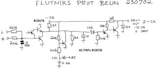
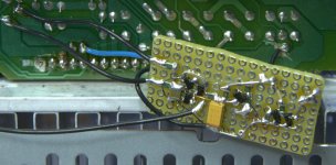
But I've solved it. I built the ugly kludge and it works like a charm. Poweron delay, poweroff immediately. DC detect at 2 V. The protect signal from the powerslab is ignored and is replaced by the output of the kludge:

I need a specially designed (LTSpice!) circuit because the protect circuitry runs off the negative rail. Fun fact: "beun" is Dutch for "kludge". "Flut" is something of low quality.
I realize now that I forgot to test for any low frequency trigger of the protect circuit. Too late...

It would certainly be nice but it is not going to happen. I closed it up and it is on its way out the door.It would be nice to figure out if you could run an unloaded higher amplitude signal without it tripping. It would narrow things down for you.
Yeah, working on a THreshold T 400 that a few others have been into. So far I've found an incorrect resistor value (it was changed) and a few other things. It had a -1.7 VDC offset on one channel. Complaint was noise on that channel. I would very much like to get out of it. It has steadily improved as I fix issues. I wish I saw it first!
With that DC offset, it should never have been released back to the customer!
With that DC offset, it should never have been released back to the customer!
Hi there
I wounder if you could help? I have been trying in vain to source both technics Power Module, SUI 3205 B & Amp Module RSN 6000 B without any real success due to cheap rip offs? Is there anywhere were you can source these genuine parts or is there an alternative permanent fix due to this being old technology? Been trying to get my amp back on line without success?
Appreciate the help
@Regenpak , thanks for sharing all details. great job and very interesting.Indeed. Enough's enough.
I found this thread when working on an issue with an SE-A900S (M2) which looks to be quite similar. When reading through it, I understand the RSN6000 was apparently fixed and worked, but the amp (A909, which is almost identical to the 900) went into protection mode at higher volume after some time (3s).
I was wondering if the amplifier at that time had a working fan connected. If not, that may explain why it kicked-off at higher volume (when it actually should start spinning - it's voltage controlled).
The RSN6000B I am working on seems at least to have a broken 2.2Ohm resistor. At least, one of them can't be measured from outside while 3 others are present (even if the drawing does not show a direct connection to the pins). Will remove the RSN and check it's value ..
@Regenpak and to all others who did follow or will find this thread, today I had a chance to replace the the 2.2Ohm SMD resistor on the RSN6000B module - the SE-900A M2 is back in live! I do not know what happend, I am not the owner, but my best guess is that the SVI module blew, and this had an impact on the RSN. The former owner may have replaced the SVI but gave up with the distorted sound.
Once again, @Regenpak , hartelijke dank voor je werk hier, toch niet voor niets geweest!
Once again, @Regenpak , hartelijke dank voor je werk hier, toch niet voor niets geweest!
- Home
- Amplifiers
- Solid State
- Help identify replacement SMD transistor