Agreed MarcelvdG! 12AX7 gets a bad rap because of lousy quality control of modern production valves. Remember the primary market for these is guitar amps where noise is preferred! 🤣

@craigtone thanks for coming to check out the discussion and comment. You've been super helpful. Me posting here is certainly not a knock on you, but a way to relieve you from the constant questions 🤣 and get a new perspective. Lots of good info shared here.He is having some serious issues with the heater supply. It is also a regulated (LT1085) DC supply. My original build had no noise or voltage issues so I have been trying to help troubleshoot but am a bit stumped since I no longer have a working unit on hand to compare.
Regarding the heater supply, I wouldn't say it's too bad. I just seem to be stuck at 5.7V for the heater supply. I think the rectifier has a forward voltage of 1.1V and rated for 2A. I think heater circuit is pulling around 1 Amp or so. I'm getting around 6.4VDC out of the rectifier - about 1:1 with my incoming AC power. When I hit my LDO regulator I have to drop a bit more, so I'm left with about 5.7VDC. I've tried another rectifier with higher current rating but forward voltage is also about the same. I've also tried a rectifier I built with diodes (1N5402) and I get the same result. If I'm understanding the detailed specs correctly one should expect some loss of voltage once current is cooking. And this loss should correlate with forward voltage of the diodes. I'm going to try some Schottky diodes that have much lower forward voltage to see if that solves my issue. I'm not sure why Craigtone did not have an issue though he also said that he remembered having to tweak the rectifier a bit. Other than it delivering under 6.3,VDC for my parallel heaters, it's doing a good job of delivering steady voltage.
I've tried a few tubes and it does make some difference but does not resolve the issue.
Frame of reference for noise is a bit scattered. I have plenty of tube guitar amps and a tube stereo (Rogue Audio). I also connect a lot of sources (tube and solid state) to my DAW as I record music at home. I don't have any gear that has a noise floor of up to around -25dB that bounces up and down like this. I'd certainly expect some character out of the tube pre but I'm thinking that something is off here. I can certainly live with it but I just wanna be sure I do the best job I can do and don't overlook something. I've got some great ideas now to run down and try to find the source of the noise though.
I do have a sample of the low frequency noise handy that I could post. The only snag is that I was only recording the left channel in that sample. I figure I should wait until I get back to tinkering this weekend before I share so that I can deliver in full stereo. Though if someone thinks they may be able to effectively "fingerprint" the noise by examining a single channel I'm happy to post later this evening. As I've said before, it isn't necessarily something you notice with your ears so much unless you're cranked up and can reproduce a lot of low end efficiently. It's more concerning watching the level meter and seeing it peak so high. I'm going to make lots of high res digital transfers of some of my out of print or rare LPs with this pre so wanna make sure to get the best results within reason.
Thanks again to everyone and especially @craigtone for joining the party!
Will do my best to reply to other questions later this evening.
Don' t you need additional capacitor between V2 anode resistor and proposed 15K series resistor ?
Now that Craigtone has replied with more details about the power supply, I'm not as confident that the 'missing' RC decoupling is causing a problem. My thinking is that it couldn't hurt, but if the B+ supply is a well regulated one with really low output impedance, there shouldn't be a problem with subsonic oscillation. But if the supply is a passively filtered one, then that could very well be a problem.
To answer the additional capacitor question, the 2nd stage 12AX7 is an inverting amplifier, while the third (output) stage 12AX7 is a cathode follower which is non-inverting. Since the 2nd and 3rd stages don't have a signal inversion between them, subsonic issues won't happen there (no phase reversal of subsonic impulses). I also assumed that there would be a bypass or decoupling capacitor shunting the B+ feeding this circuit, which means there would be a capacitor from the plate of V2a/V3a to signal ground. Therefore no, it shouldn't need an additional capacitor from there to ground.
Last edited:
As a guitar player who dearly loves my vintage tubed Ampeg and Fender amps, I feel I need to clarify this. In the guitar amp market, nobody 'prefers' noisier tubes. Higher levels of harmonic distortion, yes. Very audible tube rush, hiss and/or hum? No. Definitely no.Agreed MarcelvdG! 12AX7 gets a bad rap because of lousy quality control of modern production valves. Remember the primary market for these is guitar amps where noise is preferred! 🤣
I just got home from a long work trip and started tinkering again. I solved the issue with my regulated heater voltage by building a full wave rectifier bridge out of SB540 diodes. Now I'm able to get regulated 6.3VDC on the heaters and my rectifier is much more efficient. I haven't had time to check out the low frequency noise yet but will get back to that soon with more details. I suppose there's an off chance that I fixed it by fixing the rectifier issue but i doubt a hot overtaxed rectifier bridge would create low freq noise in the circuit.
Will follow up on various recommendations and provide noise sample as time permits. Must catch up on dad/husband/house things this weekend too!
Will follow up on various recommendations and provide noise sample as time permits. Must catch up on dad/husband/house things this weekend too!
@as_audio and others I hooked up to a scope and took some video this morning. It's difficult to capture the noise content/waveform in a still image and difficult in general to photograph (video or still) the old scope screen. But this video should show enough to explain a few things. For one, this shows the left and right channels behaving the same.I also do not trust the spectral plot - use a scope. It may be difficult to take a picture due to the
lf fluctuations, but today everybody owns a camera phone ?
It's very difficult to extract frequency content with my old scope though. As soon as I scale where I can see peaks, the thing is bouncing on and off screen too fast bc overall level is bouncing up and down. Maybe one of you with a newer scope or better FFT could take a look if I post audio files. Though perhaps frequency content is less important than the fluctuation when fingerprinting this thing.
Here's the scope video. If you haven't seen an old 1967 HP military o-scope in action, it's a sight to behold! 😊
Thank you. The scope seems to be a HP 180 (commercial designation).
I was not patient enough for watching the full length of the video.
Do we have L and R channel positioned in close proximity vertically ?
What you see is mains fluctuation or low frequency supply noise.
You may be able to "simulate" some additional filtering or bandwidth
restriction by using ac input coupling on the scope.
By the way, what does "Knottsferatu" mean ?
@as_audio sorry the video was a bit long winded. I probably could have explained a bit quicker.
Yes the L and R channels are positioned together vertically. What I was trying to show is that they are essentially doing the same thing.
The scope is a USM-281A used by the Navy. Has a Naval faceplate on the top. I think it's the same as that other scope you mentioned.
Thanks for the tips.
Yes the L and R channels are positioned together vertically. What I was trying to show is that they are essentially doing the same thing.
The scope is a USM-281A used by the Navy. Has a Naval faceplate on the top. I think it's the same as that other scope you mentioned.
Thanks for the tips.
I did not listen to any sound while watching.
Probably "intensity" is adjusted too high so that the screen appears green.
Adjust intensity and focus with a blank trace or with the calibrator signal.
Probably "intensity" is adjusted too high so that the screen appears green.
Adjust intensity and focus with a blank trace or with the calibrator signal.
Oh and @as_audio Knottsferatu is just a corny joke. That's a picture of Nosferatu (old Vampire movie from 1922) with Don Knott's head superimposed. Just a random corny joke image I picked until I find a better profile pic 🙂By the way, what does "Knottsferatu" mean ?
And yeah, there's audio of me explaining what's going on (or what I think I'm doing!).
Oh wow, that's really cool! And yes, fantastic film and fantastic film maker!Of course I know Nosferatu, "The Film That Would Change Cinema History Forever", indoor shots
have been made in the neighbourhood, but Don Knott (Knotts ?) will not be familiar for many.
Don Knotts was a popular comedy actor in the States years ago. Most widely known as a Deputy on the Andy Griffith show. Very corny and whacky.
AKA Barney Fife, one of the most human and comedic characters on the show. He was more or less the Deputy until he apparently left the show and did guest appearances as a PI in a major city. It was never quite the same without him. It's also the show that launched Ron Howard's career. Americans of a certain generation or two would certainly know who Don Knotts was and would also remember him from later on the Carol Burnett show. I'm a kid of the '60s and I guess it shows. 🤣
Back to topic : please enlighten us about the supply schematic, hv and filament, and
perhaps record the hv output voltage simultaneously with one channel on the scope.
perhaps record the hv output voltage simultaneously with one channel on the scope.
Will do. I was actually rigged up with B+ and audio output on the scope before I had to "close shop" for the day and go enjoy some family fun at the neighborhood pool. It looked like there was correlation between the two though as they were dancing up and down.perhaps record the hv output voltage simultaneously with one channel on the scope.
I'll dig in more on the high side of the circuit when I get back to my desk.
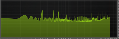
@MarcelvdG and others, I completely botched that first graph. I didn't realize that I had a slope parameter applied and did not increase to max resolution.Looking at the plot in the opening post and assuming it is a power spectral density plot with a vertical scale in dB:
Instead of dropping, the noise PSD slightly increases with frequency from 1 Hz to just below 50 Hz
It drops at a remarkably high rate between 50 Hz and 100 Hz, much steeper than the approximately -9 dB/octave you would get from 1/f noise plus RIAA correction
The 120 Hz peak is a rather wide bump; apparently the frequency resolution is not very good
As a result, my first two comments may be nonsense
It would be nice if we could get a spectrum plot with better frequency resolution
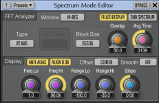
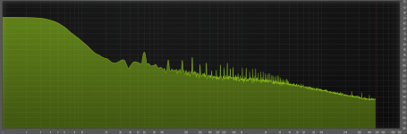
I ran the FFT again and am posting 3 photos with higher resolution and no slope applied. One shows the FFT settings I'm using in SPAN Plus, the next shows the noise in one channel with the circuit as is, and the next shows the noise in one channel with the first stage decoupler RC pole moved to 10Hz with a parallel resistor per @rayma recommendation.
Will follow-up on the HV vs. audio on the o-scope later.
Attachments
Sorry, it is pretty useless to do an investigation like this in your case if you want to decrase noise.
No worries. Thanks for your help. I will continue my investigation though because I'm trying to understand and hopefully locate the source of the noise (would prefer not to simply filter out in the input stage if possible) + learn as much as I can along the way. Even if the end result is that I leave things exactly the way they are, I'll be better off for trying. I am not nearly as proficient as many who have patiently and generously offered advice so I thank you and everyone else who have done a good job of pointing out important concepts and making thoughtful suggestions. I came along looking for good tactics and strategies, and you and others have delivered many of those. Sincere thanks again!Sorry, it is pretty useless to do an investigation like this in your case if you want to decrase noise.
- Home
- Source & Line
- Analogue Source
- Help Finding Source of Low Frequency Noise in Tube Phono Preamp