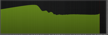
I recently built a tube phono preamp, and I am having a difficult time tracking down the source of low frequency noise (20Hz and below). My overall noise floor is bouncing up and down and peaking around -25dB or so. Per the attached graph, much of this noise is in the low frequency range. You can also see a couple of spikes around 120Hz and 240Hz likely from DC power. The attached plot was taken with inputs shorted to ground at the PCB. I have tried numerous tactics for tracking down the source of the noise, but have failed so far to figure this out. Here are a few additional facts and thoughts below:
- It almost looks like what I'd expect to see with a DC offset issue. Though the output is coupled with a 2.2uF/1mOhm RC filter which SHOULD address that issue. I'm not really sure how to measure DC offset on a phono pre or what normal range of values to expect. I have put a multimeter on the outputs and watched the voltage jump up and down. On a stereo speaker output you typically measure with the volume all the way down, but the phono pre does not have a volume control so I'd expect I can't go by guidelines typically associated with stereo speaker output DC offset measurements.
- The preamp is built around 3 12Ax7 tubes. Heaters are wired in parallel running on regulated 6.3VDC from 6.3VAC secondaries on my toroidal transformer (Antek). I'm actually running at around 5.7VDC due to some voltage loss in my rectifier bridge - about to replace that bridge with Schottky diodes to get more headroom. Would running heaters just 0.6 Volts below optimal heater voltage potentially explain my low frequency noise issue?
- I've tried tapping around with a platstic tool, pushing components, double checking solder joints, multimeter testing capacitors, moving cables around, connecting and disconnecting my star ground points from chassis, etc. None of the tactics I have tried has helped me narrow down the issue. Anyone have other ideas for things I should try to narrow down the issue?
Attachments

Yeah, that is true. I should benchmark against another phono pre that doesn't have such a high noise floor overall and see how it compares.
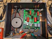
Just for reference, here is a photo of the guts. It is in disarray at the moment as I'm testing a few things and working out an issue with the heater power. I don't have any of my star ground connections running in this photo as I was doing some trial and error wiring during my tests.
Attachments
If your high voltage power supply is one with a chain of RC filters rather than a regulator, maybe it's due to slow random mains voltage variations. When I look at the output of my tube phono preamplifier with unregulated supply using an oscilloscope and zoom in enough vertically, I see the signal randomly move in and out of the picture.
If it's something with an LR8 regulator, maybe the noise of the regulator.
If it's something with an LR8 regulator, maybe the noise of the regulator.
Consider 1/f noise from your input tubes, most of this noise will be below 20Hz, and is very sensitive to operating point, reducing the plate current slightly may help. Another option would just be to try some different 12AX7A, and perhaps 5751.
Note that you can wind a few extra turns on your Antek toroid and add them in series aiding with the 6.3V filament winding, the cover may not fit. Note that increasing the filament voltage might actually make the problem worse.
Mains voltage wander can cause problems too, this can be confirmed - if the noise envelope changes significantly from measurement to measurement that may be contributing as well.
@MarcelvdG - That's a good theory that I'll try to run down. The mains go to a rectifier (FBE22-06N1), then a parallel choke (with a 20uF on each leg of the choke going to ground), then to a MOSFET (IRF840) that has a couple of parallel RC filters. Honestly I have probably neglected the mains side a bit as I seem to have tunnel vision on the heater power. Thanks for the advice.
@kevinkr - True! Tagging along with Marcel's comments, this inspires me to watch the mains voltage a bit closer to see if it is dancing in time with the noise peaks.
@rayma - haha! Fair enough! I've mostly kept my vaccum tubing to instrument amplifiers for years, but I'm trying to learn a bit more with a fun hands on project - and have a pretty great preamp on my office turntable to boot!
Before anything else, i would make sure there are no tube/socket contact problems. Next i would make sure there is no carbon composite or "cement" wirewound resistor (especially Vitrohm) anywhere. And offcourse, as allready said by mpdaudio, reflow your solder joints and make sure they are brigth and shiny.
Last edited:
Try moving the pole from the first coupling network upward in frequency, to at least 10Hz.
With that 0.1uF coupling capacitor you have now, this means the grid resistor would be around only 150k.
Though it would be preferable to have values more like 1M and 15nF instead, if you have that value around.
With that 0.1uF coupling capacitor you have now, this means the grid resistor would be around only 150k.
Though it would be preferable to have values more like 1M and 15nF instead, if you have that value around.
Good idea! I did look it over and reflowed some things initially but I'll revisit this.Reflow all your resistors solder joints. It could be a piezo like effect of a bad crystallized joint. Same with the caps, both power supply and signal.
I think I ruled out socket issues but I'll double check. I once replaced a filter capacitor in a tube amp to remedy a noise issue only up find it still occurring. It turned out to be a loose tube. Doh.Before anything else, i would make sure there are no tube/socket contact problems. Next i would make sure there is no carbon composite or "cement" wirewound resistor (especially Vitrohm) anywhere. And offcourse, as allready said by mpdaudio, reflow your solder joints and make sure they are brigth and shiny.
Good idea. The only pole I tried moving was on the output filter that's designed for DC offset (under 1Hz). Will calculate frequencies on the other RCs.Try moving the pole from the first coupling network upward in frequency, to at least 10Hz.
With that 0.1uF coupling capacitor you have now, this means the grid resistor would be around only 150k.
Though it would be preferable to have values more like 1M and 15nF instead, if you have that value around.
Wow, you've got some good eyes to spot the 1M resistor paired with that 0.1uF film cap. That's a good idea though since existing combination -3dB point is around 1.5Hz. I will probably just swap the resistor or try one in parallel to see how it goes first. I honestly had considered a different film cap after I realized how poorly the giant 0.1 caps fit into the space on the PCB.Try moving the pole from the first coupling network upward in frequency, to at least 10Hz.
With that 0.1uF coupling capacitor you have now, this means the grid resistor would be around only 150k.
Though it would be preferable to have values more like 1M and 15nF instead, if you have that value around.
All, by the way, this circuit is very similar to the WAD (World Audio Designs) Phono 3. First coupling network includes grid stopper resistor after the coupling cap. Schematic is similar to the WAD one posted here: https://www.lencoheaven.net/forum/index.php?topic=28177.0
One other thing I did not mention...I have a resistor on each side (left right) for a 75us corner. I used single slot terminal posts for these resistors because I wanted to try things out with and without this resistor - and I considered installing a switch for the two options. In hindsight I think I'll just solder this resistor in. They're making good contact and are "in the circuit," but seems like another opportunity for noise with the terminal posts there. Maybe not...
@rayma I'll definitely try increasing the pole, but would also be concerned a bit that I'm not addressing the root of the problem. This is a good mitigation/compromise if I can't tame the noise. There's always some concern with fidelity and missing out on some source freqs, but it's debatable how much I'd notice if I was rolling of frequencies at a 10hz high pass filter.
I'm loaded up with some good ideas here. Thank you all! I'm a bit of a hack at this and am still trying to fill a lot of gaps in my knowledge so I appreciate all the thoughtful info shared.
I won't be able to tinker again until this weekend, but at least I'll have a good battle plan and some time to think things over.
Replacing the 0.1uF capacitors with 0.047uF or 0.022uF may help, but may affect the accuracy of the LF time constant at/below 3183us, and therefore it will also affect the flatness of your LF response below 100Hz. Is the noise actually causing a problem in your system - or is this just an attempt to make a worthwhile (and possibly unachievable) performance improvement?
When I was designing my muscovite series of phono pre-amps I ran into some pretty serious 1/f problems with the 6J9 pentodes I was using in one of the iterations and ended up with a cascode instead. (The threads are still here if you search for them.)
When I was designing my muscovite series of phono pre-amps I ran into some pretty serious 1/f problems with the 6J9 pentodes I was using in one of the iterations and ended up with a cascode instead. (The threads are still here if you search for them.)
That's a good idea though since existing combination -3dB point is around 1.5Hz. I will probably just swap the resistor or try one in parallel to see how it goes first.
If temporarily reducing the 1M to 150k substantially reduces the LF noise, then you'd be better off reducing the
first coupling capacitor down to 33nF instead, and keeping the 1M grid resistor. (My earlier 15nF was a math error.)
That sets the pole at about 10Hz, but will not cause a subsonic peak like the smaller resistor and larger capacitor will.
It's always better to use a grid resistor significantly larger that the previous plate resistor, to avoid the subsonic peaking.
Also the smaller capacitor will have smaller parasitics as well.
Last edited:
- Home
- Source & Line
- Analogue Source
- Help Finding Source of Low Frequency Noise in Tube Phono Preamp