Theses look reasonable. The rest I can't make sense of. "... but same 4v+ as before to ground! How is that happening?!" I'm afraid I can't follow what you're measuring and where meter is connected.R46= 76v
Q24 base = 0.0
Q24 emitter no= 0.6
Q25 base = 0.6
D10= 0.6
D12= -1.3
Let's get some more measurements with respect to collector of Q29, black lead on collector.
Approximate anticipated readings are:
Q24 base 0mV
Q24 emitter 0.6V
Q24 collector ??
Q25 base 0.6V
Q25 emitter ~ 0V
Q25 collector 0.6V
Q9 base 1.2V
Q9 emitter 0.6V
Q9 collector ??
Please measure with red probe on transistor leads when possible and advise your readings.
Thanks.
+4v referenced to ground is the difference between the base and emitter referenced to ground. But they measure 0.6v between them, so I'm confused as to how that happens.
Q24 base 0mV
Q24 emitter 0.6V
Q24 collector -9.3
Q25 base 0.6V
Q25 emitter 0.1V
Q25 collector 0.8v
Q9 base 1.0v
Q9 emitter 0.8V
Q9 collector 120V
Thanks again!
Peter
Q24 base 0mV
Q24 emitter 0.6V
Q24 collector -9.3
Q25 base 0.6V
Q25 emitter 0.1V
Q25 collector 0.8v
Q9 base 1.0v
Q9 emitter 0.8V
Q9 collector 120V
Thanks again!
Peter
Hi Peter,
Again, sorry for slow response.
I'm suspicious that you have an open trace between the collector of Q25 and the emitter of Q9, so that there's no current flowing in Q9. In my list of points to check (post 221), I was trying to suggest measuring directly on the transistor's lead. In other words, I was asking voltage at both ends of a connecting trace; the schematic may indicate there'll be equal voltage at two points, but that may not be the case. Simplest test is to check power-off continuity of collector of Q25 to the emitter of Q9, lead to lead.
As to how the two test procedures could have different results:
Assume that suspected trace is open. When you connect one meter lead to collector of Q29 and probe Q9 emitter, the meter's resistance provides about 10M connecting resistance, so the voltage at Q9 emitter will appear reasonable.
In contrast, a meter tied to ground with 10M resistance would pull a floating Q9 emitter into reverse breakdown, and might produce the observed 4.1V discrepancy.
I'm not certain of this theory, but it fit's most of the symptoms. In any event, there's some defect preventing conduction in Q9. If the suspected trace is intact, take transistor voltages at Q27, Q29, Q24, Q25, Q9.
You confirmed these ~0.65V with powered, in-circuit voltage tests? These are base-emitter voltages?
Sorry, those previous were power off.
These are powered:
Q27:0.61
Q29: 0.59
Q24: 0.62
Q25: Black probe on base, red on emitter: 0.7- 0.9 quickly hunts in this range, not stable
Q25: red on base, black on emitter: 0.67
Q38: 0.68 with probes either way.
Q9: 0.31
These are powered:
Q27:0.61
Q29: 0.59
Q24: 0.62
Q25: Black probe on base, red on emitter: 0.7- 0.9 quickly hunts in this range, not stable
Q25: red on base, black on emitter: 0.67
Q38: 0.68 with probes either way.
Q9: 0.31
Last edited:
I had to mull on this, hence slow reply.
I'm not sure how you performed the measurement in #226. The two measurements of Q25 lead me to guess that you might be making "Diode Test" measurements with the power applied? In Diode Test mode, the meter itself supplies a test current and the data it presents is valid only if there's no applied power other than the meter. I was assuming voltage measurements with power on; reversing the leads should only flip the sign of the displayed magnitude. What's going here: "Q25: Black probe on base, red on emitter: 0.7- 0.9 quickly hunts in this range, not stable"?
Let's go back to the configuration of #213 and #214, because it presented a stark, 4.1V inconsistency. Let's not leave that point until we figure out what's happening.
Thanks!
Q25, power on, when measuring with the black probe on base and red probe on emitter, it reads about 0.9V mostly, but jumps around a bit, to add low as 0.7. Reversing the probes gives a steady 0.68V.
Q24 still shows ~0.6 between base and emitter, but when measuring both to ground there's ~4V difference.
Q24 still shows ~0.6 between base and emitter, but when measuring both to ground there's ~4V difference.
Last edited:
By any chance, do you have two meters?
Perhaps there is still some oscillation, leading to erratic results when the various points are probed. I believe there's still a 22K providing feedback (refer #191), so let's change connection so that the 22k connects between R56 and +16V. This change removes feedback and should force Q30 base more positive than Q31 base, and so C26 voltages should swing to the negative rail. Check if Q24 base and emitter voltages re ground now make sense. Please describe what happens.
Next, please move the 22k resistor to -16V. C26 voltages should swing to the positive rail. Please check Q24 base and emitter as above and describe these results also.
Thanks.
Hi.
Okay, 22k from R65 to +16: C26+V, Q24 base/emitter to ground ~5V difference.
22k to -16V: C26+V(still), Q24 base/emitter to ground ~4V difference.
Doesn't look to be behaving as expected (hoped).
Thanks again,
Peter
Okay, 22k from R65 to +16: C26+V, Q24 base/emitter to ground ~5V difference.
22k to -16V: C26+V(still), Q24 base/emitter to ground ~4V difference.
Doesn't look to be behaving as expected (hoped).
Thanks again,
Peter
Good morning.
So I interpret that the C26 node is stuck on the positive rail, irrespective of bias imposed on Q31 base. There was some suspicion that oscillation was confusing DC voltage measurements, but these experiments suggest closed-loop oscillation is extremely improbable.
Note that with -16V driving the 22k, C26 should properly peg on the positive rail, yet the observed ~4V base to emitter of Q24 phenomenon persists. If you are not able to find a defect with suggestions offered below, don't hesitate to change back to +16V where the expected result is C26 on the negative rail.
In the interest of collecting as much info as possible, with -16V driving the 22k, would you report bases of Q30 and Q31 voltages re ground.
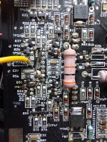
So returning to the 4V base-emitter puzzle: referring to the schematic, there are three components joined at the Q24 emitter: Q24 emitter, Q25 base, D10 cathode. Would you measure voltages re ground of these three connection points, directly on the component leads--- thus exposing possible open traces.
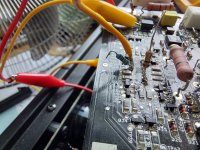
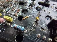
Would you post a closeup pic of the suspect area so I have visual reference?
Thanks again.
So I interpret that the C26 node is stuck on the positive rail, irrespective of bias imposed on Q31 base. There was some suspicion that oscillation was confusing DC voltage measurements, but these experiments suggest closed-loop oscillation is extremely improbable.
Note that with -16V driving the 22k, C26 should properly peg on the positive rail, yet the observed ~4V base to emitter of Q24 phenomenon persists. If you are not able to find a defect with suggestions offered below, don't hesitate to change back to +16V where the expected result is C26 on the negative rail.
In the interest of collecting as much info as possible, with -16V driving the 22k, would you report bases of Q30 and Q31 voltages re ground.
So returning to the 4V base-emitter puzzle: referring to the schematic, there are three components joined at the Q24 emitter: Q24 emitter, Q25 base, D10 cathode. Would you measure voltages re ground of these three connection points, directly on the component leads--- thus exposing possible open traces.
Would you post a closeup pic of the suspect area so I have visual reference?
Thanks again.
Hi Peter,
Thanks for the photos!
So the emitter of Q24 continues to measure 4V lower than its base, measured in two individual measurements---in other words, voltage re ground at base of Q24 followed by measuring Q24 emitter re ground. Of course, these two voltages shouldn't coexist. Would you also provide the voltages seen at terminals of Q9 to give a more complete picture?
Any chance you own two voltmeters?
I surmise that the 22k test resistor was connected to -16V during the above tests. Next, would you connect it to +16V and repeat the measurements in #232, including voltages at Q9? (This test should deliver voltage at C26 toward the negative rail.)
Many thanks.
Hi!
I do own two voltmeters.
Q9@ -16V: -71.4, 48, -72
+16V:
Q30: 0.2, 14.5, -0.4
Q31: 0.1, 14.5, -0.6
Q24: -73.6, -76.5, -69
Q25: -69, -68.8, -69.8
D10: -69, -68.4
Q9: -68.3, 45.4, -68.8
I do own two voltmeters.
Q9@ -16V: -71.4, 48, -72
+16V:
Q30: 0.2, 14.5, -0.4
Q31: 0.1, 14.5, -0.6
Q24: -73.6, -76.5, -69
Q25: -69, -68.8, -69.8
D10: -69, -68.4
Q9: -68.3, 45.4, -68.8
We still have the baffling ~ 4V base emitter drop, but I do prefer the +16V on the 22k test resistor. It makes the data slightly more consistent.
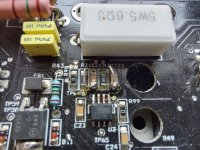
I'm wondering if Q25 is really conducting current. According to above voltages, there should be about 6.7V across R43, i.e. [-76.5V - (-69.8V)]. That's about 0.3W dissipation and R43 is indicated to be a 1/4 W resistor, so it should feel hot. Does it? Do you find 6.7V across its terminals?
Please tell me about your voltmeters in case we need to use them simultaneously.
Thanks.
With power off, make an in-circuit resistance test of R43. You should find about 150 ohms, maybe less with surrounding paths.
Well, shoot! I was hoping R43 would be found to be open.
I tend to trust the measurements, and toasty Q9 and Q11 are consistent with voltage across R43. What still does not make sense is the apparent base-emitter voltage at Q24, especially since data suggests 45mA flowing through the Q25, Q9, Q11, Q38 transistor chain. Would you measure drop across R76--- it should also be roughly 6.8V, similar to R43 drop.
[As an aside, the observed voltages make sense: the schematic even notes "2 x 2.2mA" tail currents in the input stages. This implies nominal 6.6V drop across R46, leading to a similar drop at R43. You report 6.8V across R46. That's about 0.31W. The R43 package is under-sized and should be 1/2 W, but that's not the present problem.]
So let's return to the Q24 4V base-emitter phenomenon. Would you reconfirm the voltages reported earlier, i.e. the 4V drop persists, then connect one voltmeter from the base of Q25 to ground in a hands-free arrangement. That will leave the other meter free to probe other nodes.
First confirm the two meters agree at base of Q25. Then probe emitter of Q24, then base of Q24. Of course, watch for any change of the first meter's reading. What happens with readings? If you probe Q24 base-to-emitter, any change? This was the baffling data noted in an earlier post. I'm hoping these experiments will make something become clearer.
Thanks.
P.S. I keep forgetting to mention to look at the working channel for reference/confidence.
Last edited:
- Home
- Amplifiers
- Solid State
- Help!!! Dumb-a$$ ham first mistake content