@artosalo
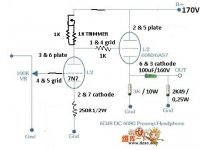
The attached schematic isn't my design, how to be improved?
You could use something like 250R in the 7n7 cathode. That would give about 8mA current. Without analyzing the entire circuit, I think that should still provide sufficient swing.
The 7N7 has the exact same internal construction as a 6SN7, but more readily available in NOS, as the loctal sockets are less popular.
If using a gyrator, the input voltage to the gate of the top FET would be set at around 120V.
Thanks for usefull information.
What do you do for 7N7, gyrator or only CCS with two DN2540, what have the best SQ & is more reliable?
I have on hand SK170 & DN2540.
What do you do for 7N7, gyrator or only CCS with two DN2540, what have the best SQ & is more reliable?
I have on hand SK170 & DN2540.
Last edited:
Thanks for usefull information.
What do you do for 7N7, gyrator or only CCS with two DN2540, what have the best SQ & is more reliable?
I'd build it with a single DN2540 per section and try it. It will be easy to try a cascode or gyrator later. Reliability should be good. 6SN7 types are as rugged as tubes get. Can't comment on SQ. That's a matter of personal taste, and depends on the entire system - including the choice of headphone.
I have 220R 0.5W or 270R 0.5W for the cathode resistor of 7N7, wich one will be better for 8mA?
Headphones are Sennheisser HD600 with 300 ohms of impedance.
Headphones are Sennheisser HD600 with 300 ohms of impedance.
Last edited:
According to your schematic, at 1.33mA, you'd have about 133 volts on the 7n7 plate. At the cathode, you'd have about 2.9V. If you want these about the same (maybe anything over 2V (-2V grid to cathode) on the cathode should be fine). Then look at the plate curves and pick the combination of current, and voltages in this range for your operating point. Play with different values of current and cathode resistor until you get values in the range you want.
I'm sorry, I'm lost, I believe to improve the schematic will be without changing B+ 170V in place of 100K anode resistor load use one DN2540 & change the cathode resistor for 250R, it's right?
Last edited:
Last edited:
I'm sorry, I'm lost, I believe to improve the schematic will be without changing B+ 170V in place of 100K anode resistor load use one DN2540 & change the cathode resistor for 250R, it's right?
Yes. If you use 270R, it might be OK or you may need to lower the current on the CCS a little. You can try 270 and measure the voltages at the plate and cathode. It won't be off enough to cause any harm. Same for 220R, and maybe need to raise the CCS current a little.
If you are going to play with tubes, you need to learn how to use the plate curves to set your operating point. There are tutorials on the net.
Sheldon
Last edited:
You are right Sheldon, I have to learn more, I forgot the calculation to screw load lines with CCS is more easy. Load Line says for 8mA grid 0 volts and 75V on anode, I think are these the right values to be measured once the cathode resistor and the one DN2540 installed?
Using an anode load resistor 38K5 = 5 times plate resistance of 7N7 (7K7) and I will need B+ of 308V to get the 8mA.So no way to anode resistor load without changing the power transformer.
Plate 91.5V & 105V
Cathode 1.79V & 1.67V
Both triodes CCS set 8mA.
Grid 0.315V & 0.003V
Using an anode load resistor 38K5 = 5 times plate resistance of 7N7 (7K7) and I will need B+ of 308V to get the 8mA.So no way to anode resistor load without changing the power transformer.
Plate 91.5V & 105V
Cathode 1.79V & 1.67V
Both triodes CCS set 8mA.
Grid 0.315V & 0.003V
Attachments
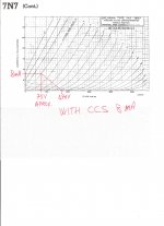
Felipe, CCS loadline is horizontal (for example at 8mA).
If you cathode resistor is 250R, bias voltage is -2V, thus your operating point is about 8mA, 120V, -2V bias.
Input voltage max. swing 0...4V.
-4V curve at 8mA about 165V, so 170V B+ is not enough for CCS loading, must grow to 190-200V.
If you cathode resistor is 250R, bias voltage is -2V, thus your operating point is about 8mA, 120V, -2V bias.
Input voltage max. swing 0...4V.
-4V curve at 8mA about 165V, so 170V B+ is not enough for CCS loading, must grow to 190-200V.
Thanks Bela.
B+ 189.5V (only for 7N7)
Cathode resistor is 220R
Plate 94V & 110V
Cathode 1.86V & 1.805V
Grid 0.24V & 0.003V
Bela the other B+ available is 277V what resistor value have I to use to reduce to 200V?
B+ 189.5V (only for 7N7)
Cathode resistor is 220R
Plate 94V & 110V
Cathode 1.86V & 1.805V
Grid 0.24V & 0.003V
Bela the other B+ available is 277V what resistor value have I to use to reduce to 200V?
Bela the other B+ available is 277V what resistor value have I to use to reduce to 200V?
Read Bela's initial post more carefully. He has it correct. Your grid voltage is always 0V under static conditions. The values on the plate curves reflect the difference between grid and cathode. If the cathode resistor drops 2V, then the grid is at -2V relative to the cathode. If your signal exceeds 2Vpp (or 1.4vRMS), then the grid will swing positive, relative to the cathode, on the positive swing. This amp is not designed to operate at positive grid voltage - will clip if you do.
I have not analyzed the output section, but doubt that you will need more than 2Vpp to drive your headphones.
Sheldon
Using an anode load resistor 38K5 = 5 times plate resistance of 7N7 (7K7) and I will need B+ of 308V to get the 8mA.So no way to anode resistor load without changing the power transformer.
I thought your intent was to use a CCS instead of an anode resistor. The "5 times" rule of thumb is irrelevant if you are using a CCS or gyrator. Their impedance is in the megaOhm range. If using a resistor you want a high value to get a relatively shallow load line - lower distortion. With a CCS, as Bela noted, the loadline is essentially horizontal (i.e., no change in current as the voltage across the CCS changes).
I'm sorry my ignorance there is a way to improve the 6H13C part of the schematic?
Ok took a quick look here. I'm assuming the 6H13C is something close to a 6080? If so, there are a few things to consider:
This amp is DC coupled, which means that the grid of the output tube is at the voltage of the input anode.
It also means that you need operating conditions such that the voltage at the cathode is 20-40V higher than the grid, in order to bias the tube. If your plate voltage at the input tube is say 100V, the cathode voltage of the output tube would need to be, let's say 130V. That means that the effective plate voltage for the output tube is 40V (170-130). Looking at the plate curves for the 6080, that looks too low for good linearity.
Do you have the actual original schematic, with the original component and B+ values?
BTW, While you do some thought experiments, it helps to draw a schematic and plug in the expected voltage/current values at each node.
One other aside: There will be pretty high DC potential at the output with this design. The only thing between that and the headphones on your ears, and across your brain, is an electrolytic cap. Better make sure that's well over rated for the voltage. Even so, I'm tempted to recall the words of Dirty Harry; "you feeling lucky punk? - well are you?"
Do you have the actual original schematic, with the original component and B+ values?
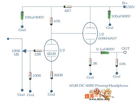
The original schematic is based ECC88/6DJ8 + 6AS7/6080 tubes.
Mod to use 7N7/6SN7 by v4lve lover diya member:
"You can check the datasheet for the 6SN7 for reccomended anode grid leak and cathode resistances. @ 150V B+ The anode will then hopefully bias up at +80V with respect to ground. Then you can choose whether to have the tube directly coupled to the 6080 or to include a RC bias circuit.
6AS7 OTL headphone amplifier
Output cap is MKP 82uF 400V.
Become too complicate to use 7N7 as front end, could I use the original schematic without any problem with ECC88?
Bela I have tried with B+ 277V for only 7N7 but the plate at the voltage don't change and B+ at 6AS7 lowered to 130V more or less, can be my power tx don't have enough power for both tubes.
Become too complicate to use 7N7 as front end, could I use the original schematic without any problem with ECC88?
It's no problem to use the 7N7 with a CCS. The original design calls for 80V at the plate of the 7N7, which is also the voltage at the grid of the 6080. I'll assume the output stage works OK with that. So, if you want 80V at the 7N7 plate, I'd go with something like 2mA and size the cathode resistor to give about 2.5V at the 7N7 cathode. That would be a cathode resistor of about 1.25k.
A couple other points:
The original B+ calls for 150V. A B+ of 170 should be OK too.
You need to keep a separate 100k grid leak resistor on the grid of the 7N7 (as in the original schematic). If you don't have that, and the input pot wiper fails, the tube will run away.
Also, no need for the resistor from input plate to the 6080 grid. You would want if if the input/output grid connection were cap coupled.
Sheldon
The 100k grid leak resistor on the grid of the 7N7 is always used because I use AVC at the output.
- Home
- Amplifiers
- Tubes / Valves
- Help CCS for 1.33mA