I read it in an other thread..
"A valve bushing is pressed into the cylinder head... becoming smaller in the process.
The bushing is then machined for a loose fit to the valve about 0.002-0.004" (0.05 - 0.1mm) this is to allow room for the valve to expand with temperature (more for exhaust valves).
A valve could make a good spindle provided the clearance to the bushing was greatly reduced... say 0.0006 - 0.0008 inches. Oil film will consume the gap and provide a tight yet smooth bearing.
You can purchase shaft, bushing and hubs though... not so expensive.
"
http://www.diyaudio.com/forums/showthread.php?s=&threadid=70115
don't know if right..
Hey all:
Just caught up with this thread - some interesting stuff here.
One thing no one has mentioned yet is the lateral stress on the bearing when in operation. The pull exerted on the bearing by the tension of the belt (string, tape, whatever...) is the single fly-in-the-ointment with a tt bearing. It might not seem like much, but it actually adds up to a significant factor. Without this, an ideal tt bearing would be easy.
As many have noted, the weight of the platter - however massy, is not a problem: shaft + cup + hard ball = done! Considering the very small point of contact, the potential source of vibration (i.e. rumble) is small also. With an oilite sleve bearing of the type used in most lo to mid-fi factory tables, the surface contact between the shaft and sleve is also small. Add in the centrifugal inertia of the whole spinning bit, the end result could run at the reqd. 33 rpm as silently as the a banker when you are trying to get a refund.
BUT! (there's allways a but, isn't there?) when you exert force in one latteral direction on the assembly, and when that force is levered by the distance of the drive belt centerline from the support point of the bearing, the shaft is pressed against the bearing in a line between the platter spindle and the motor. Result - uneven wear and rumble, multiplied by the un-circularity of both parts (hey, nothing is EXACTLY round).
So, the real challenge is not supporting the load, it is dealing with the latteral thrust applied by the drive belt.
Just my 2 cents worth...
Jess
In my simple design I turned a fast spiral on the shaft which hopefully lifts oil up the bearing from the closed end where the 2 ball bearings
that cope with the end thrust live.This enables the shaft to be a reasonable sliding fit (lower friction ) in the inverted top hat bush ,a
small well was turned in the top of the bush to prevent oil being pumped (aka archimedese ) all over the plinth .this seems to do the trick there is no bearing noise at ridiculously loud levels motor noise
being predominant (no room to separate it from the main plinth)
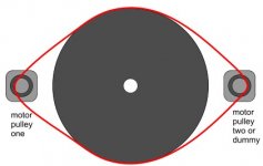
1 motor, 1 dummy motor, 1 solution
Jesseg,
wouldnt the side thrust problems you mention be cured with the 2 motor pulleys setups ive seen on some units?. i.e. 180 degrees each side of the bearing, this would cancel out the leverage you mention
indeed you could have 1 'real' working motor and a 'dummy' pulley on the other side🙂
did anyone read my 'floating' magnet bearing proposal whereby you can throw the ball bearing in the trash can?
no?
Attachments
Eggsy ,
would not the act of placing an lp and possible clamp on the platter require a settling time before the tt could be used? I envisage it floating up and down inresponse to added weight.
would not the act of placing an lp and possible clamp on the platter require a settling time before the tt could be used? I envisage it floating up and down inresponse to added weight.
Hi Baggins,
yes I thought of that and i imagine the sheer mass of the platter would cure any 'bouncing' problems, these magnets are astonishingly powerful! though they would have to carefully selected for 'tuning' the weight of the vinyl and clamp would be taken into account.
just imagine having *no ball bearing* grinding away at the bottom!
also neo's are [unlike conventional disc magnets] self-centering, they would actually hold the spindle true-to-centre all the time!
did i think of this first or has it already been invented i wonder?...but knowing my luck... 🙁
the verdier turntables use similar magnetic bearings.
no balls...
http://jcverdiervalvevinyl.online.fr

no balls...
http://jcverdiervalvevinyl.online.fr
The system I used was a small radius bearing in the end of the spindle
running on a slightly larger one in the bottom of the top hat sleeve bearing .There is no rolling noise as such. theoretically its point contact
in an oil bath ,as I said before its inaudible compared to the motor hum and vibration if I remove the belt and spin up the platter by hand .It does though contribute to the transmission of any other induced noises being by its very nature a direct transmission path to the platter.If your convinced that the magnets will be stable in platter height.then I think they would be superior.
Jesseg,wouldnt the side thrust problems you mention be cured with the 2 motor pulleys setups ive seen on some units?. i.e. 180 degrees each side of the bearing, this would cancel out the leverage you mention
Yep - to some extent, and several have done it - mostly found in the exotic european designs. I guess the reason it is not accepted as a universal solution is 'cause it adds so much gear to the system - another bearing (source of noise and vibration) another belt, and the alignment, footprint, etc.
I just wanted to bring up the issue of latteral thrust because the folks here are thinking about DIY bearings, and no one had mentioned this major component in the design requirements
did anyone read my 'floating' magnet bearing proposal whereby you can throw the ball bearing in the trash can?
There was a monster thread on this a few months ago. The problems with magnetic bearings are:
1 - the presence of a huge magnetic field in fairly close proximity to a very sensetive magnetic sensor (the cartridge). Unshielded, a magnet strong enough to support platter and all will overcome your cartridge completely and might even damage it.
2 - again the magnetic field cannot be biased to compensate for latteral thrust. To cope with the sideways pull of the drive belt you will still need a bearing of some sort and this defeats the advantages of the mag bearing.
In spite of this there are mag bearing tables out there. I would be inclined to study them carefully and see how they have dealt with these issues.
Jess
Just to make sure we're all talking about the same phenomena here
isnt rumble indicative of some kind of rotating ball support i.e the sound of individual balls in a ball race bouncing over dirt and irregularities in the lower track. is the term really applicable to the types of bearing we're discussing?
isnt rumble indicative of some kind of rotating ball support i.e the sound of individual balls in a ball race bouncing over dirt and irregularities in the lower track. is the term really applicable to the types of bearing we're discussing?
isnt rumble indicative of some kind of rotating ball support i.e the sound of individual balls in a ball race bouncing over dirt and irregularities in the lower track. is the term really applicable to the types of bearing we're discussing?
As I understand it, rumble is any noise (vibration in the audio spectrum) produced by a bearing when in operation. Rumble isn't the only nasty output from bearings that effects playing vinyl, just the worst. And, rumble was such an issue in years past that some pre 70's preamps had a rumble filter designed in to them to block signals from the cartridge below 35Hz.
PS: I don't think I have ever see a ball or roller bearing used for the main spindle in a turntable.
Jess
Fair enough if you mean any bearing induced noise but i come from way back then and remember rumble as variable low frequency
noise on garrard SP 25 mk11 's and BSR 's etc I dont think it was even considered a problem on Thorens , Goldrings etc. of the era.
noise on garrard SP 25 mk11 's and BSR 's etc I dont think it was even considered a problem on Thorens , Goldrings etc. of the era.
i come from way back then and remember rumble as variable low frequency
You are absolutely right about the tables listed, but as I said, it was a sufficiently widespread problem that electronics of the day had built in compensation.
With today's new materials (like Teflon), rumble is much less of a problem, but it is not gone. If it was, someone would have invented the perfect turntable bearing and we all would not be having this conversation....

I kinda like it that there is still room for us hobyists to improve the state of the art
Jess
Anyone looked at Funk Firm Vector Drive? 1 motor with 2 additional puleys? Real clever and it works.
Been playing the Funk Vector TT for a few weeks now and it is wicked good.
Been playing the Funk Vector TT for a few weeks now and it is wicked good.
Am I right in thinking that the sp25 did indeed use a ball thrust race
on top of the short sleeve bearing?
on top of the short sleeve bearing?
From baggins
Am I right in thinking that the sp25 did indeed use a ball thrust race
Very possible, and there may be any number of others. I have never see one in my 30 years in the hobby (or maybe I just forgot)
From tubenut
Anyone looked at Funk Firm Vector Drive? 1 motor with 2 additional puleys? Real clever and it works.
NOW WE'RE TALKIN! This is the best implementation of the idea I have ever seen. Most of the previous attempts have been along the line of the design posted by Eggzy a few back - large and dependant on very precise alignment.
This looks gooooood! Where can I get more detailed info, tubenut?
Jess
Indeed it did, in common with the vast majority of Garrard tables over the years. BSR used a virtually identical system. It was almost certainly the main reason for the rumble though🙂Am I right in thinking that the sp25 did indeed use a ball thrust race
Yup, the Garrard AT6 (AuTochanger) and its derivative the SP25 (Single Player) used a ghastly sleeve bearing with a thrust race of six small bearings that I wouldn't use on my bike. This was common to all "designs" that derived from autochangers.
I used sintered bronze in my turntable design but just for the record, turning at 33 1/3 rpm does not create enough friction to allow the sintered bearing to work properly. I've spoken with a manufacturer of sintered bearings and confirmed my thoughts on this.
My next bearing design incorporates 2 vespel bushings in an aluminum housing. Vespel is a very expensive performance plastic and something I've worked with in the past. I also plan to incorporate a heater in the bearing housing to control thermal expansion, although vespel is extremely stable.
The inverted bearing will be pretty exotic in that the bearing will be fully submerged in an oil bath. That is the single drawback to inverted bearings and this design eliminates that. The thrust end will be a tungsten carbide disc laminated to the upper stainless steel housing. The bearing housing is actually a 2 piece design.
I've built a few sapphire bearing supports but my latest platter will weigh approx. 32 lbs so I chose tungsten carbide.
I have been busy sourcing the tungsten carbide pieces and heater, god knows trying to find a manufacterer for 1 or 2 prototypes is very time consuming but I'm getting there. The heater is the last obstacle but I do a lot of thermal work so I think I can get that together soon.
- Status
- Not open for further replies.
- Home
- Source & Line
- Analogue Source
- HELP!!! anyone sourced a DIY bearing?