Yes, it is called CMCL. See the red boxes at the attached schematic...
Hi Valery
I just had a closer look at this and I don't think the red boxes constitute a CMCL.
They seem to be conventional Current Mirror "helper" transistors.
The current stability seems to be achieved by a conventional Cordell style resistive load.
This does work and I don't doubt that the amp performs well.
But I don't see a Common Mode Control Loop there, unless the VAS constant current sources play some part that is not obvious.
Best wishes
David
...In more detail: to prevent saturation of Q3 and Q4.
Hi Edmond
Nice to see you still keep an eye on the subject.
Any more work on DiAna?
My next amp should be so clean that it will need a really excellent distortion analyser.😉
Best wishes
David
Hi Valery
I just had a closer look at this and I don't think the red boxes constitute a CMCL.
They seem to be conventional Current Mirror "helper" transistors.
The current stability seems to be achieved by a conventional Cordell style resistive load.
This does work and I don't doubt that the amp performs well.
But I don't see a Common Mode Control Loop there, unless the VAS constant current sources play some part that is not obvious.
Best wishes
David
Hi David,
You are right, this is a helper transistor, however, if we look closely on how the whole arrangement works (resistors between LTP outputs play important role as well) - the mechanism is described in detail by Bob Cordell - the quiescent current of the VAS is established so that it depends directly on the tail current of the LTPs (common mode regulation). There is no feedback to LTP's tail, however having it dependent in one direction seems to be enough for the purpose. In cooperation with DC servo, operating in differential mode, the whole circuit completely balances itself.
Cheers,
Valery
/OT
Hi David,
>Any more work on DiAna?
Indeed, still busy with DiAna. At the moment, I'm rewriting large parts of the code. Till now, I relied on many standard functions of Win32, but they behave differently under XP, W7 respectively W8, which I don't like, of course. So I'm writing my own code for things like a title-, menu- or status-bar, as well as my own buttons. Admittedly, rather boring to do, but the quirks of the various window version are even more boring.
>My next amp should be so clean that it will need a really excellent distortion analyzer.

Hope you have a decent sound card and reliable ASIO drivers.
Cheers, E.
Hi David,
>Any more work on DiAna?
Indeed, still busy with DiAna. At the moment, I'm rewriting large parts of the code. Till now, I relied on many standard functions of Win32, but they behave differently under XP, W7 respectively W8, which I don't like, of course. So I'm writing my own code for things like a title-, menu- or status-bar, as well as my own buttons. Admittedly, rather boring to do, but the quirks of the various window version are even more boring.
>My next amp should be so clean that it will need a really excellent distortion analyzer.
Hope you have a decent sound card and reliable ASIO drivers.
Cheers, E.
Last edited:
Hope you have a decent sound card and reliable ASIO drivers.
I have a Creative Audigy 4 card at the moment, not your favourite brand😉
But I am ready to buy a better card, depends on what is best when the time comes.
I have an oldish machine so the PCI slots are native, avoids some problems that you noted.
And Windows XP is at least stable, now they don't try to "fix" it any more.
Best wishes
David
Hi Ziggy and David,
In more detail: to prevent saturation of Q3 and Q4.
Cheers, E.
Diodes D1 to D4 are to minimize any saturation of the input transistors and so help with overload conditions.
They do not normally stabilize the current of the VAS.
Edmont, Dave,
Many kind thanks for your inputs.
Any sense in lavish radiators for the TO-92 input stage transistors ?
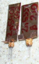
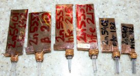
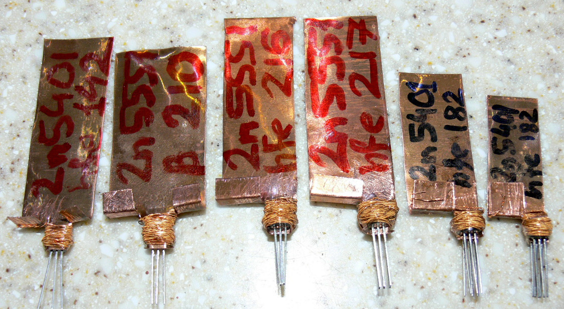
I'm kind of like considering driving them rather hard ... The "singles" are for current sources / sinks. The "pairs" are beta matched (~0,6%) and thermally closely coupled ...
Cheers, Ziggy.
Attachments
Last edited:
...the quiescent current of the VAS is established so that it depends directly on the tail current of the LTPs (common mode regulation). There is no feedback to LTP's tail...
Yes, I noticed the feed forward, but that is not really a CM Control Loop.
But, as you point out, the servo is involved too and it is not obvious to me if there is really a CMCL or if it is just the Cordell resistor load that does the work.
I need to think more or experiment with a simulation, pity you have not switched to LTSpice to make it easier to share.
Best wishes
David
Any sense in lavish radiators for the TO-92 input stage transistors ?
...The "pairs" are beta matched (~0,6%) and thermally closely coupled...
They look wonderful! Nice to see such a creative, low cost solution.
Certainly should help stability to have them thermally coupled, and lower temperatures can't hurt.
Op amp designers like to increase the LTP current for several reasons.
They say to turn it up until the silicon smokes.😉
The heat-sinks/radiators will provide you with a bit more flexibility or safety factor.
Best wishes
David
Many kind thanks for appreciation. Just trying to squeeze the maximum juice out of those tiny, high beta, high voltage, small pF, high transition frequency TO-92 toddlers.They look wonderful! Nice to see such a creative, low cost solution.
Indeed, I firmly believe that "good sound" need not cost a fortune, to be discernible as such. My two basic principles are: KISS + BF. (Keep It Simple and Stupid + Brutal Force). Whatever knowledge I do not yet possess, I tend to catch up on with BF & KISS. Such "green grass" strategy has proven me very lucky in my tinkering till date. The down side is the kilograms. My last amp is c.a. 70kg. BF comes at a price of "kg". Till recently fiddled only with tubes and otl's; this is but my very first transistor based power amp. It may well happen that some rather basic questions may follow ...
Since purchasing the opto stuff anyways, might as well make an opto-attenuator / opto-volume-control to go with it, from the front-end side. I did my opto-attenuator based on pairs of led-->photo-resistors. It works ... bizarre, but quite well, actually. The upside is that there is no wiper within such a pot. The downside(s) - are there, but not to an extent so as to totally discard such an idea from the outset. They are ... manageable.my sim of a optoisolator VAS current sense mirror bias cmcl
What is the best application to read / browse these simulation files (.cir) and where do I download it from ? .. Most presumeably some Spice or other - but there are may different flavours / origins of those, yes ?Hop here comes the circuit :
oh yes why are the clamps for? security against what?
I should go out and buy some copper sheet.....................
Any sense in lavish radiators for the TO-92 input stage transistors ?
I'm kind of like considering driving them rather hard ... The "singles" are for current sources / sinks. The "pairs" are beta matched (~0,6%) and thermally closely coupled .......
0.2mm, or 0.3mm, or 0.5mm?
http://www.diyaudio.com/forums/atta...topology-construction-troubles-p1120002-b.jpg
He already did.. look at post 466
He already did.. look at post 466
Last edited:
I said:
I did not say "go out and buy"
I then asked "what thickness?"
I should go out and buy some copper sheet.
I did not say "go out and buy"
I then asked "what thickness?"
Yes, it is called CMCL. See the red boxes at the attached schematic - this is one of my "high speed" designs, works perfectly - balanced and stable. At the time I developed it Dave Zan pointed me to look closer at CMCL concept - helped a lot.
If somebody is interested - I've got a live prototype, PCB, etc.
Extremely low distortion. One of the specialties - class A drivers (CCS-loaded)...
Cheers,
Valery
I use it on my design, but now I know the name 😀
I think it is EFA (Emitter Follower Augmented)
Attachments
Last edited:
What is the best application to read / browse these simulation files (.cir) and where do I download it from ? .. Most presumeably some Spice or other
LTSpice is the de-facto standard for most people.
Free from Linear Technology - Home Page
Has a few quirks but is unrestricted, hard to beat.
Best wishes
David
Maybe it is "zener noise" ? Did you try to replace the Z1 and Z2 with a "string" of forward biased diodes ? Just curious ...Update :
I shorted Z1 and Z2 in my previous schematic and it changed something. I have no more RF oscillations all the way up to 10MHz. The trace looks always clean (I mean without RF oscillations).
Z.
I used a 0,1mm copper sheet ... simply had such stuff in the drawer ... from a Modellers suplies store..I should go out and buy some copper sheet.
0.2mm, or 0.3mm, or 0.5mm?
That's thinner than I guessed would be useful.
Can you tell if 0.1mm thick is effective?
I use 10times thickness as effective radius for very good conductance of heat in an aluminium heatsink.
Copper being much better probably performs as well at 15times radius for very good conduction.
Accepting "only" adequate conductance at 30times thickness gives 6mm diameter for 0.1mm thick.
So I need guidance on effectiveness.
Too early to say. Not in the "real testing" stage yet. But should be OK. These are very small TO-92's. Copper is a good conductor. This thickness allows you to "model" the shape of the copper "around" the transistor. After glueing the "central" flat piece of transistor to copper, I use the "side wings" of copper to wrap around and then press on with the additional wire.That's thinner than I guessed would be useful.
Can you tell if 0.1mm thick is effective?
Just a wild guess concept - feel free to modify as per your individual gut feeling and taste. I just happened to have that particular thickness avaliable from another project.
I could imagine that 0.2 would still be flexible / workable, but providing more heat conduction ...
- Home
- Amplifiers
- Solid State
- HEEEELLLPPP : M. Randy Slone Mirror Image Topology Construction - Troubles