Hi Damir,
I will do that, but shouldn't we start a new thread, as class-I etc. has nothing to do with the Randy Slone amp?
What about this title: "A Closer Look at Class-I and his Siblings"
Cheers,
E.
I will do that, but shouldn't we start a new thread, as class-I etc. has nothing to do with the Randy Slone amp?
What about this title: "A Closer Look at Class-I and his Siblings"
Cheers,
E.
Hi Damir,
I will do that, but shouldn't we start a new thread, as class-I etc. has nothing to do with the Randy Slone amp?
What about this title: "A Closer Look at Class-I and his Siblings"
Cheers,
E.
Hi Edmond, I agree, please start a new thread as those are all yours ideas.
I tried to incorporate this(last) OPS with my input stage but I have problem with phase margin if OPS is init FB loop. I will post it in the new thread.
Damir

Hi Stein,
Too bad.Can you tie the HD on another PC? Much change to recover most of your data.
Cheers,
E.
Hi Edmond
It seems like I was able to recover most of the files.
As a birthday present to myself 😀
I built a new PC using:
Intel Core i7 Quad processor
12 GB RAM
HD1: 120GB SSD (for WIN7 and programs)
HD2: 1 TB HDD for storing files
Silent GeForce graphics processor
The PC runs simulations very quickly and is very silent.
Cheers
Stein
What about this title: "A Closer Look at Class-I and his Siblings"
Cheers,
E.
I think it's a good idea to open a new thread about "Class-I and his Siblings"
Cheers
Stein
Last edited:
I think it's a good idea to open a new thread about "Class-I and his Siblings"
Cheers
Stein
Nobody noticed but the thread is here. http://www.diyaudio.com/forums/solid-state/202684-class-i-siblings.html.
Damir
Hi Edmond
It seems like I was able to recover most of the files.
As a birthday present to myself 😀
I built a new PC using:
Intel Core i7 Quad processor
12 GB RAM
HD1: 120GB SSD (for WIN7 and programs)
HD2: 1 TB HDD for storing files
Silent GeForce graphics processor
The PC runs simulations very quickly and is very silent.
Cheers
Stein
Hi Stein,
Wow, that looks really good and fast. I would have configured it exactly the same way. With W8 it will run even faster. BTW, regarding the SSD, is it a SLC or a MLC drive?
Cheers,
E.
Last edited:
Hi Edmond, everyone,
It's been nearly 2 years now since I worked on my amplifier project.
I hope you guys are doing fine !
I don't know if anybody will pick up this message but what about continuing what was started here?
Curious to see any replies...
In the mean time cheers to you all
Olivier
It's been nearly 2 years now since I worked on my amplifier project.
I hope you guys are doing fine !
I don't know if anybody will pick up this message but what about continuing what was started here?
Curious to see any replies...
In the mean time cheers to you all
Olivier
Hi Olivier,
How's it going?
As you see, I'm still alive, though a little older.
Any progress with your Amp?
Cheers, E.
How's it going?
As you see, I'm still alive, though a little older.
Any progress with your Amp?
Cheers, E.
Hi Edmond,
Nice to hear from you !
I am a little ashamed to admit that the testprobe is still on the pcb at the exact same spot as 2 years ago... So apart from a thick layer of dust there is no progress at all.
I would like to pick it up however.
I have access now to MC10 for simulation and AD13 for pcb design ... but I need to re-import things and refresh my mind on where it was left off ... that is always though to do ...
Did you work on something in particular lately?
Cheers, Oli4
Hi Olivier,
Accordong MC, there are five possible PCB layout netlist formats that the schematic can be converted into: Protel 1, Protel 2, Accel, Orcad PCB II, and PADS. Does it mean you can't import the schematic to AD13 directly? (I'm a noob in this regard ).
).
>Did you work on something in particular lately?
/OT
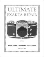
Yes, though in a different field: Vintage camera repair. BTW, I just received a hard to get manual (see pic) how to do that the right way. Now I can use my sound cards not only for THD measurements, but also for adjusting the shutter speeds of a camera. 😀
Cheers, E.
Accordong MC, there are five possible PCB layout netlist formats that the schematic can be converted into: Protel 1, Protel 2, Accel, Orcad PCB II, and PADS. Does it mean you can't import the schematic to AD13 directly? (I'm a noob in this regard
).>Did you work on something in particular lately?
/OT
Yes, though in a different field: Vintage camera repair. BTW, I just received a hard to get manual (see pic) how to do that the right way. Now I can use my sound cards not only for THD measurements, but also for adjusting the shutter speeds of a camera. 😀
Cheers, E.
Attachments
Hey guys. I started soldering / building the input stage and driver stage and came to a certain level of advancement in the process, according to the Mr. Sloan book, Figure 11.14 schematic, which is basically the complementary mirrors and complementary mirrored VAS stages, ... which gave the start of the "HELP" post no. 1. with this thread. After browsing through the multiple pages of this thread, now I am in deep depression. I do not even know "where to start". Out of these multiple pages of discussions, did you actually come up with some sort of consensus as to the simple and most effective "fix" of the flaw in the mirrored Sloan topology ? I guess that what I am asking about is not the "BEST of the World" type of solution, but rather a fairly simple one, that will "deal" or take care of the instability problem with not to much over-complicated additional circuitry ? Where do I "START" ?
Please be gentle on me, as this is my "first" transistor amp that I am building.
Cheers and many thanks for some initial pointer.
Ziggy.
Please be gentle on me, as this is my "first" transistor amp that I am building.
Cheers and many thanks for some initial pointer.
Ziggy.
Bob Cordell discusses the same issue in section 7.3 of his book, Designing Audio Amplifiers, ISBN: 978-0-07-164025-1.
Basically, the suggestion was to use a 'helper transistor' to shift the LTP current mirror voltage another Vbe drop away from the associated rail and introduce a resistive load across the LTP collectors to make the VAS quiescent current predictable and stable.
Basically, the suggestion was to use a 'helper transistor' to shift the LTP current mirror voltage another Vbe drop away from the associated rail and introduce a resistive load across the LTP collectors to make the VAS quiescent current predictable and stable.
Bob Cordell discusses the same issue in section 7.3 of his book, Designing Audio Amplifiers, ISBN: 978-0-07-164025-1.
Basically, the suggestion was to use a 'helper transistor' to shift the LTP current mirror voltage another Vbe drop away from the associated rail and introduce a resistive load across the LTP collectors to make the VAS quiescent current predictable and stable.
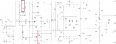
Yes, it is called CMCL. See the red boxes at the attached schematic - this is one of my "high speed" designs, works perfectly - balanced and stable. At the time I developed it Dave Zan pointed me to look closer at CMCL concept - helped a lot.
If somebody is interested - I've got a live prototype, PCB, etc.
Extremely low distortion. One of the specialties - class A drivers (CCS-loaded)...
Cheers,
Valery
Attachments
Bob Cordell discusses the same issue ...
use a 'helper transistor' to shift the LTP current mirror voltage another Vbe drop away from the associated rail and introduce a resistive load across the LTP collectors to make the VAS quiescent current predictable and stable.
When I checked this I found the helper transistor is not strictly necessary.
It is possible to balance the mirror with careful utilisation of VAS transistor(s) base current(s).
But whatever method is used to balance, I still found the resistive load was undesirably sensitive.
It is worth while to simulate it and check mismatched Hfe, temperature and the like, for your own application.
Yes, it is called CMCL. See the red boxes at the attached schematic - this is one of my "high speed" designs, works perfectly - balanced and stable. At the time I developed it Dave Zan pointed me to look closer at CMCL concept - helped a lot...
The resistive load is not really a Common Mode Control Loop.
The CMCL specifically stabilizes the Common Mode, the resistors are less discriminate.
Nice to see it worked well for you.
Best wishes
David
Last edited:
replace the two mirrors with 4 resistors as collector loads to the complementary LTPs.
You may want to increase the LTP gain to take account of the loss of gain by removing the mirrors.
You may want to increase the LTP gain to take account of the loss of gain by removing the mirrors.
Hello Edmond,Okay, my turn. 😀
Below you see another approach how to define and stabilize the VAS current.
The inputs of the VASes are connected via 10k resistors (R18/20) to the bases of the current sources, which act as a temperature compensated reference (more or less).
At 27 dgrs. Ic = 8.4mA, increasing to 9.5mA at 0 dgr. and decreasing to 7.5mA at 50 dgrs.
By varying R12/13 you can tailor Ic according to your needs.
I am in the same project with the same difficulties, trying to find an optimal solution for my Sloan derived mirrored diff Input Stage / complementary VAS stage.
Can you please explain to me what is exactly the fuction that the diodes D1 .... D4 perform and how can they "stabilize" the current of the VAS stage ?
How does this diode thing work ?
Cheers,
Ziggy.
Hello Edmond...
Can you please explain to me what is exactly the fuction that the diodes D1 .... D4 perform and how can they "stabilize" the current of the VAS...
Edmond is a bit quiet lately, note the date of his post, so if I may take the liberty to respond.
Diodes D1 to D4 are to minimize any saturation of the input transistors and so help with overload conditions.
They do not normally stabilize the current of the VAS.
Best wishes
David
- Home
- Amplifiers
- Solid State
- HEEEELLLPPP : M. Randy Slone Mirror Image Topology Construction - Troubles