Hi All,
I know this is an amp section but I'm guessing that you tube-people could help a brother out!
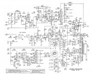
I got this unit recently, recapped it and fired it up. The 1V2 tube doesn't light up at all, and I'm guessing that it's related to the reason the scope has no vertical gain whatsoever (although I can change the spot position).
I tested the voltage from the transformer at the socket positions at around .588 volts, which seems to be in the operating range?
Do you think I just need another tube, or do you need more info?
Thanks in advance!
I know this is an amp section but I'm guessing that you tube-people could help a brother out!
I got this unit recently, recapped it and fired it up. The 1V2 tube doesn't light up at all, and I'm guessing that it's related to the reason the scope has no vertical gain whatsoever (although I can change the spot position).
I tested the voltage from the transformer at the socket positions at around .588 volts, which seems to be in the operating range?
Do you think I just need another tube, or do you need more info?
Thanks in advance!
Attachments
Long time since I worked on valve stuff.
The 1V2 (V9) supplies the HT to the CRT... so it's not that 🙂
Measure the DC voltages around V1 and V2 particularly the Anodes of V2 and the Cathodes of V1
Edit... if voltages are missing check PSU around rail "A" fed from that 1.5k resistor around V10.
The 1V2 (V9) supplies the HT to the CRT... so it's not that 🙂
Measure the DC voltages around V1 and V2 particularly the Anodes of V2 and the Cathodes of V1
Edit... if voltages are missing check PSU around rail "A" fed from that 1.5k resistor around V10.
Last edited:
Wow - hey nice to hear from you Mooly, been awhile!
Hmm, well it seems that the 1V2 should be working as you say, visual inspection threw me off, and of course, I'm a noob...😱
I'll have to wait a bit to check voltages, as my multimeter didn't like the taste of 1200+ volts...😱
However, I poked around some more and found that V1 (6AB4) seems to be non-functional. That tube stands alone behind a shield, so I kind of forgot about it. Seeing that its right smack in the middle of vertical input/gain/etc., it makes sense that this could also be the culprit.
I pulled V1 right out and restarted. Well, everything else that was working before was still working.
So what do you think? Should I check the voltages on V1 from the socket/pin positions to the chassis prior to replacing the tube?
Thank You!
if you can move the spot up and down you can eliminate(90%) the vertical output/drivers of the display tube esp if the display moves up and down a lot( off the screen ). V1 the input vertical tube is a voltage follower/impedance converter and will have gain ~=1 or less. Most of the vertical gain come from v2a and v2b.
set you meter to 100mv AC,
set scope to the highest gain setting both selector and vernier pot,
follow the ac signal through scope,
be very careful of high voltages.
if you look at the crt tube notice the driver tube plates are connected to the crt. One tube pulls up the other pushes up. yes a push pull circuit. On the other half of the ac signal the rolls are reversed. ie pushes down, pulls down
your scope is AC coupled so your gain readings from stage to stage should be measure in ac volts. Dc is used to position and centre the beam.
I noticed the other day my old tube Heathkit scope that I bought new in 1969 is not working anymore either so I may have a look at it some time this fall and see if I can get it going again for nostalgia sake.
I count at least 5 Ac coupling capacitors. If any of them are leaking dc they might throw off the bias of the next stage and ruin the gain.
Last edited:
Thanks for the reply. I can move the spot horizontally off screen. Vertically is more limited, about an inch away from the top, or the bottom. (so about a 3 inch vertical span)
I didn't replace any of the mica caps, but I did replace all the rest. That, of course, might not matter entirely I know.
When you say set the meter to 100mv AC, what exactly should I be connecting it too?
Take Care
I didn't replace any of the mica caps, but I did replace all the rest. That, of course, might not matter entirely I know.
When you say set the meter to 100mv AC, what exactly should I be connecting it too?
Take Care
If you have a spot and can move it, the problem is in the low level circuits. You need to get the sweep working and the vertical signal path. Check the power supply.
What's the DC voltage on pin 1 of V2A and pin 6 of V2B
What's the DC voltage on pin 7 of V1 ?
I will check that, but I'll have to get back to this project, maybe next week, as there is nothing more I can do without my multimeter working correctly.
Thanks Everyone -
What you could try... bearing in mind high voltages are nearby... is this. Disconnect that 0.1uf cap on the vert gain pot wiper and touch pin 2 of V2A (the end of that 10 meg) with a long metallic screwdriver and see if there is any movement or jumping of the trace. That's like "buzzing" the input of an amp.
That would help determine if the fault were in V1 or V2 stage.
On safety... that point is at essentially zero volts, but it's normal practice to only delve into working valve stuff with one hand, and keep the other hand away from the chassis or anything that's earthed. That way there's no possibility of a shock "across" you.
What you could try... bearing in mind high voltages are nearby... is this. Disconnect that 0.1uf cap on the vert gain pot wiper and touch pin 2 of V2A (the end of that 10 meg) with a long metallic screwdriver and see if there is any movement or jumping of the trace. That's like "buzzing" the input of an amp.
That would help determine if the fault were in V1 or V2 stage.
Just tried that and its the first time I've seen any vertical amplitude. Thanks!
The biggest difference when I turned it on, there was a rise in ripple/noise, so I imagine the cap probably smoothed that out before. Touching pin 2 of V2A causes +/- vertical jumping, alot or a little depending contact/tapping. Holding the screwdriver to the pin gives a steady-state rise in the amplitude.
So it certainly looks like the V1 stage is the issue.
On safety... that point is at essentially zero volts, but it's normal practice to only delve into working valve stuff with one hand, and keep the other hand away from the chassis or anything that's earthed. That way there's no possibility of a shock "across" you.
the other hand (behind my back) ------>

Last edited:
Guess so... either the valve itself or one of the resistors gone high. Check the 3.9K in the PSU that feeds that valve as well. It does feed the sync separator too and that may not be working too and you wouldn't know yet if the 3.9k were open circuit.
If you mean the 3.9k resistor at F - Delta (B + 115), I measured it and got 4.2k. This seems within range as this resistor is rated at 10% tolerance (silver/4th band).
The voltage measured at pin 1 of the V1 cathode follower, measured 145vdc. (nice neighbor lent me the multimeter).
So my next question is, if this tube looks dead, is it? I've been fooled by this before...
The voltage measured at pin 1 of the V1 cathode follower, measured 145vdc. (nice neighbor lent me the multimeter).
So my next question is, if this tube looks dead, is it? I've been fooled by this before...
What's the DC voltage on pin 1 of V2A and pin 6 of V2B
What's the DC voltage on pin 7 of V1 ?
Pin 1 of V2A = 61.9
Pin 6 of V2B = 91.2
Pin 7 of V1 = 0
If pin 1 is high and there is no voltage on pin 7 that means V1 is not conducting for whatever reason. Can you see the heaters lit up? Try reinserting the tube a few times to clean up the connections. Don't suppose you have an extra 6AB4 laying around.
Craig
Craig
Thanks for the reply. No this tube isn't lighting up at all. I scrubbed everything thoroughly and tried re-seating it a half dozen times.
Most likely I'll order one tonight.
Most likely I'll order one tonight.
Pull the valve out and see if you can read continuity across the heater pins on ohms.
Pin 1 is the Anode... 145v on here suggests no current being drawn by the valve.
What's the voltage on pin 7 ?
If it's wrong check the four resistors connected "directly" to the valve pins 6 and 7. If they are OK then disconnect the two caps that go to pins 6 and 7 and check the voltages again on pin 7.
If it's still wrong the valve or it's heater supply is duff.
Pulled the tube, There isn't any continuity/resistance across its heater pins. (the x/x on the socket itself has continuity between the 2, and continuity all the way back to the transformer)
No voltage reading on Pin 7.
Resistors on 6/7 are spot on.
I can't disconnect the caps right now, but a quick check of the values is right on.
No voltage reading on Pin 7.
Resistors on 6/7 are spot on.
I can't disconnect the caps right now, but a quick check of the values is right on.
Well now I'm waiting patiently for the replacement tube thank you.
I was just thinking about overall safety on this project, and while I am still alive, I was wondering if you thought replacing the old 2 conductor cord (hot/neutral) with a 3 conductor cord (hot/neutral/earth) was a good idea. The cord had to be replaced, so I used the heavier cord with the earth attached to the chassis.
Also, what do you suggest on testing for any live voltages after I unplug the unit. Meter the power cord? I'm just wondering about shock from the assembled chassis before I slide it back into the case.
Thanks.
If it originally used just two core lead then it must have been designed to be safe I would have thought... even way back then. If you ground the case it has to be OK safety wise... just remember that the ground lead of the probe is then tied to mains ground and so you must never touch that lead to anything at a different potential or else it will just put a short across it. With the scope "floating" that isn't an issue... although there are very real safety implications of working like that.
The only shock risk when unplugged is from any electroylitics that stay charged up... impossible to say if hat will happen in practice... just always assume they are unless you measure across them to prove otherwise. You can't get a shock from the power cord as it's isolated via the mains transformer.
The only shock risk when unplugged is from any electroylitics that stay charged up... impossible to say if hat will happen in practice... just always assume they are unless you measure across them to prove otherwise. You can't get a shock from the power cord as it's isolated via the mains transformer.
- Status
- Not open for further replies.
- Home
- Design & Build
- Equipment & Tools
- Heathkit Oscilloscope O-12