How accurate is your LCR meter?
You can trim capacitors by adding smaller caps in parallel to raise the total capacitance.
You can trim capacitors by adding smaller caps in parallel to raise the total capacitance.
Hi Bill,
it's a XWJ01 half bridge with Kelvin clips and is a 4.5 digit device, from what I've seen its very accurate, only goes up to 7.8 KHz from 100hz, but otherwise on the same level of the DER-EE 5000, with which i've compared it with (a friend of mine owns a DE5000), getting similar results down to the last digit with film and ceramics and a bit more with electrolithics.
A note on adding caps to reach a specific value, they must have the same chemistry right? i.e. PP film with PP film, ceramic with ceramic...
I'll start experimenting adding caps in parallel and series to see practical results tonight.
Thak you for your help,
Franco
Small capacitors used for trimming a parallel combination should be as ideal as possible. Tight tolerance, near zero temperature coefficient, low drift over time are all desirable. Ceramic NP0 best meets these requirements. When the capacitance value needed is above the range for ceramic NP0 then use polypropylene.
Implementing the LT1468 -- the HA3-2625-5 looks like it was a bit tricky to compensate and now unobtanium. There's a trimpot to adjust the LT1468 balance. In the interest of clarity, bypass caps have been omitted from the schematic, except those recommended by LLTC/ADI for the LT1468. Will figure out how to switch the AGC:
Attachments
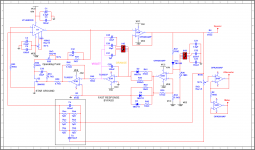
jackinnj, Nice schematic, but I think I see a couple of missed connections: a wire from U1 + input to the junction of R52 and R30; a missing ground at R106.
I concur with Bill_P comments about capacitor dielectric choices--- polyesters are reputed to be inferior to either polypropylene or NPO. I suggest PCB layout that would accommodate adding parallel caps to below-nominal caps. e.g. 5uF = 4.7uF+ empirical trim caps.
Close tolerance capacitance will aid frequency accuracy but, more important I believe, is that ratio consistency across the four bands will ease the adjustment range imposed upon the FET; minimizing the required control range (aka control authority) allows the FET to have minimal sinewave amplitude and reduced distortion.
Last edited:
Thank you jack! i see... I'm looking at the various mods you've done to the schematic - but why the OPA2604AP? I get a host of warnings when I try to look it up on Mouser, it seems to be not readily available... could it be also substituted with a LT1469? it's pin to pin compatible
The OPA2604 has the same pinout as the OPA2134, just accommodating Multisim. There are newer parts from TI.
I have a lot of ADI's analog switches, so I show an ADG409 (but the project is now turning into a bit of a monster.)
I missed C24 -- 15nF
I have a lot of ADI's analog switches, so I show an ADG409 (but the project is now turning into a bit of a monster.)
I missed C24 -- 15nF
Attachments

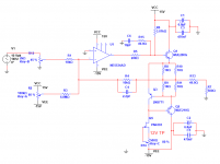
Ah ok!The OPA2604 has the same pinout as the OPA2134, just accommodating Multisim. There are newer parts from TI.
I have a lot of ADI's analog switches, so I show an ADG409 (but the project is now turning into a bit of a monster.)
OK, makes sense and the ADG409BRZ is also readily available. What would you use for the actual selection of the AGC caps?
Asking simply because range selection is still made thru a rotary switch.
So I was thinking, maybe add a second ADG409 to also do range caps selection and control everything with a simple 4 position single pole rotary switch (to use the front panel control layout)...
And yes it's a monster, but it's great!
While an appealing thought, I do not think an IC mux for switching the bridged-T tuning components is a good idea--- I believe distortion would suffer greatly. An IC mux for the AGC should be tolerable because it's in the ALC path where distortion isn't much of an issue.
P.S. You could always use two DPDT relays to handle cap switching and then use the simple rotary switch you mentioned. That would also make mux address connection easier at the same time. 🙂
P.S. You could always use two DPDT relays to handle cap switching and then use the simple rotary switch you mentioned. That would also make mux address connection easier at the same time. 🙂
Last edited:
While an appealing, I do not think an IC mux for switching the bridged-T tuning components is a good idea--- I believe distortion would suffer greatly. An IC mux for the AGC should be tolerable because it's in the ALC path where distortion isn't much of an issue.
Ahhh too bad. There's still the problem of selecting the AGC caps on the PCB at the same time as the discrete parts on the rotary switch though.
Jack's most recent schematic incorporates my suggested sensing of the selected capacitor path. I sure hope it works as imagined...
On further reflection, I really like your idea of using a a simple switch for band selection. That would make the board general purpose in the sense that it wouldn't have to exist in a Heath IG-18 chassis--- it could be a from-scratch instrument.
On further reflection, I really like your idea of using a a simple switch for band selection. That would make the board general purpose in the sense that it wouldn't have to exist in a Heath IG-18 chassis--- it could be a from-scratch instrument.
Ahh I see, the sensing network is the one below the schematic, ok.
I see where A1-A0 should be connected, but I cannot figure out where E1 -E0 should go, I'm still too green to recognize all conventions used in circuits, sorry
I see where A1-A0 should be connected, but I cannot figure out where E1 -E0 should go, I'm still too green to recognize all conventions used in circuits, sorry
E0 and E1 are taps in the decade rotary switch in post #77. If you're adopting the 100:1 cap ratio, something different would be required.
I believe the Enable pin can be connected directly to +15V.
I believe the Enable pin can be connected directly to +15V.
You are totally right and I apologize. Must be the heat or something. I completely forgot about that post and I even commented it.
I believe the Enable pin can be connected directly to +15V.
Then you get two switch positions were A0=A1= 00, and switch 1 is ON.
Hi Jack,
Thanks for challenging my approach. There may well be a flaw in my reasoning--- it certainly won't be the first. 😱 But let me try to convince you that that it works. I'm prepared for embarrassment.
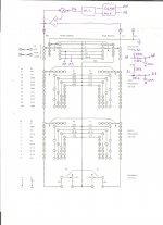
I've attached a truth table that depicts my interpretation of the Range switch. Table entries in columns E0 and E1 are: J(ground), K(opamp output), or Open circuit. Adjoining columns A0 and A1 show the presumed outputs after the pull-up/LPF networks.
Thanks again for critical review.
Steve
Thanks for challenging my approach. There may well be a flaw in my reasoning--- it certainly won't be the first. 😱 But let me try to convince you that that it works. I'm prepared for embarrassment.
I've attached a truth table that depicts my interpretation of the Range switch. Table entries in columns E0 and E1 are: J(ground), K(opamp output), or Open circuit. Adjoining columns A0 and A1 show the presumed outputs after the pull-up/LPF networks.
Thanks again for critical review.
Steve
Attachments
Hi! I think that we're reaching a VERY interesting point.... I see that many ancillary components have been left out on the schematic Jack posted, and that there are some details to be clarified, but as it is, the ideas are great.
could we think about laying out a board? I would do it, as I am learning DipTrace, however I am afraid that I would need too much tutoring. If someone helps me though, I can try...
could we think about laying out a board? I would do it, as I am learning DipTrace, however I am afraid that I would need too much tutoring. If someone helps me though, I can try...
Hi Jack,
Thanks for challenging my approach. There may well be a flaw in my reasoning--- it certainly won't be the first. 😱 But let me try to convince you that that it works. I'm prepared for embarrassment.
I've attached a truth table that depicts my interpretation of the Range switch. Table entries in columns E0 and E1 are: J(ground), K(opamp output), or Open circuit. Adjoining columns A0 and A1 show the presumed outputs after the pull-up/LPF networks.
Thanks again for critical review.
Steve
I think K is going to the Inverting input of U1 which works -- I had to take a look at the switch!
I agree with the truth table.
X1 = S4 closed
X10 = S3 closed
X100 = S1 closed
X1000 = S2 closed
- Home
- Design & Build
- Equipment & Tools
- Heath IG-18 IG-5218