If you have a uTracer you could trace a set of curves with the two different heater voltages, keeping to the two extremes of the voltage @ 300mA and 6.3V. Keep the anode voltage as stated in operating characteristics, sweep the grid from cutoff to zero, and capture both sides by measuring the other side with the screen (g2) measurement, and tie the grids together.
It will be easier to visualise the effect than the just the single point on the curve as seen on the oscilloscope.
Ra looks to be high and current low in the quickest view, pointing to a tired tube?
It will be easier to visualise the effect than the just the single point on the curve as seen on the oscilloscope.
Ra looks to be high and current low in the quickest view, pointing to a tired tube?
What is not understandable is why to bear heavy currents from socket to socket and not keeping the heavy currents away using separate leads with necessary currents for each only ? This is what I do, as simple as can be without no wiring complication:

The whole method I used to do a simple straight 'T' wire conection and keep the heavy currents rail away here: https://music-electronics-forum.com...amps/build-your-amp/979103-soldering-question

The whole method I used to do a simple straight 'T' wire conection and keep the heavy currents rail away here: https://music-electronics-forum.com...amps/build-your-amp/979103-soldering-question
Last edited:
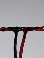
All I do with AC filament wires is twist the two wires together in a variable speed drill. Twisting the wires provides some shielding.
Regarding HT tube rectification, is there a preferred wiring method. I gather that at high voltage electrostatic dominates, and at high current it is electromagnetic, but in either case the twisting cancels it out.
Running HT cables close to the chassis or twisting them seems like asking for trouble so would it be better to use something like coax cable? Will be cancellation effect work on the rectified voltage going to the choke/capacitor?
For the filament (or heater tied to cathode) cable, I gather it should be okay to twist the cables but there will need to be sufficient isolation to the chassis.
Isn't earth commonality from input to output?
If so, hot wire, must be corridored esp beyond 450dc
you see how it's done using centering manes & isolators porcelain, identical scenarios, linesmen grooming the high voltage utility power lines
If so, hot wire, must be corridored esp beyond 450dc
you see how it's done using centering manes & isolators porcelain, identical scenarios, linesmen grooming the high voltage utility power lines
Just use wire with the right voltage rating. Read the specs and choose the right type for your purpose. Think not only about the voltage (safety) but also about the current (heat / loss).
Regards, Gerrit
Regards, Gerrit
How about running 6.3VDC and 240VDC along 1.2 meter together? Is it better to separate those two different voltages, or do you have any recommendations to improve this situation.
The red marked wires and parts are 6.3VDC circuit. 6.3VDC is supplied by a LM317 regulator.

The red marked wires and parts are 6.3VDC circuit. 6.3VDC is supplied by a LM317 regulator.
Why are you distributing 240Vdc through that top socket? Do you have a schematic? Is there no secondary side fusing, or other protection scheme?
Is the big valve a twin diode rectifier? It doesn't have ss diode protection on each anode.
Is the big valve a twin diode rectifier? It doesn't have ss diode protection on each anode.
It’s a dual chassis phono stage and this part is the power supply. That’s why there’s 240vdc through that socket. These sockets will be replaced btw.
There only one fuse, at the AC inlet.
The big tube/valve is a 6C4P rectifier tube.
I’ve got no schematic of the power supply, because it’s a commercially available product and there’s no schematic supplied. Closer to a schematic than these circuit boards is not possible at this moment. These boards are the latest versions of the circuit, only material and layout differ from the version I’ve got. It’s a Ampearl RE2030 SE LCR phono stage.
Ta. So back to your initial query. What is your concern with running wiring together? DC wiring with multiple rails is run in the same cableform for many applications. Do you think there is a safety, or noise, or ?? issue. Can you identify how/where the 0V of the 240Vdc supply is linked to the 0V of the 6.3Vdc supply, and how/where there is a link from those 0V nodes to chassis gnd?
- Home
- Amplifiers
- Tubes / Valves
- Heater Wiring - the Good the Bad and the Ugly