
Thanks, hifijim!!Nice! quite a change from what you currently have.
I hope to get your opinion on how they compare when an A/B is set up.
...
Used the DATS3 on the phl 6201.


The model tracks best around the EBP. The FS was higher than the +/-5 hz range that PHL specifies. But the cone has not been asked to play much. After 20 min of a 50hz sine, the FS dropped down 1hz. I am very happy with how both drivers are pretty much identical. The fs was 1hz apart. Does PHL use mitosis to make drivers?
Driver porn:


The inside of the PE box. I used loctite II for the wood and the globbed on some loctite "quick&thick" on all of the inside seams with my fingers.
Now I am waiting for things to dry. I only had 4 clamps so I had to squeeze the box all around the box to get the glue out before putting the clamps in a central spot.
These are the screws I am using:
https://en.toutlehautparleur.com/set-of-16-hexagon-socket-wood-screws-5-x-30-mm.html
Next up is a little wood protection and then some measuring!
Last edited:

phl 6201 has a single coat of "tried&true" for moisture protection. The woofer is not screwed in yet for a few measurements.

The updated T/S params don't change the previous sim


The mic was about 1cm from the cone. SPLs were calibrated.
I have a 4.9db boost with a second-order shelf and a second-order XO on the woofer. I will do a raw measurement later. It was neat to see VCAD match again with an enclosure sim. I do see some issues around 350hz but there is no stuffing in the box for these measurements.
The phl 6201 is still face up but I have been able to listen to music through just the woofer and a rough XO to the 8" mid.
My first thought was "ok, low GD does matter" and the second was "this thing just paints bass".
I can't wait to hear it in the proper spot with better timing.
....
Tried a few diff. things inside the phl 6201 box.
mel = 0.5" of melamine foam
stuff = 1.5 bags of polyfill
I also tried nothing in the box and eq to remove resonances.


There should be a second order xo around 150hz so none of the humps past that are wanted.
My first thought was "ok, low GD does matter" and the second was "this thing just paints bass".
I can't wait to hear it in the proper spot with better timing.
....
Tried a few diff. things inside the phl 6201 box.
mel = 0.5" of melamine foam
stuff = 1.5 bags of polyfill
I also tried nothing in the box and eq to remove resonances.
There should be a second order xo around 150hz so none of the humps past that are wanted.
Attachments
This data is from back when I was trying to figure out the XO. It is a 70-degree measurement. It looks like I had something close or the top of the mid box is reflecting the tweeters sound. It is cool to see how similar it is. If my math is correct, the reflection is 40mm away. This reflection could go away when I move the tweeter forward or I had a diff. speaker too close when measuring. Or maybe it is something else?


It is the same graph but with 4ms and 40ms after the impulse.
On axis when I was moving the tweeter up and down to find the xo:


Changing the setting back to the graph defaults:

It will be interesting to see what gets cleaned up with a better baffle. The square foam should be chewing up some of this.
It is the same graph but with 4ms and 40ms after the impulse.
On axis when I was moving the tweeter up and down to find the xo:
Changing the setting back to the graph defaults:
It will be interesting to see what gets cleaned up with a better baffle. The square foam should be chewing up some of this.
I have a new thread for testing delays on a couple of sines:
https://www.diyaudio.com/community/...es-with-different-delays.388217/#post-7070858
I've been trying to make some audio clips to test out some ideas on the GD and phase.
I am interested in testing how changes in phase and the baffle interact. I made a clip of a 500hz-1500hz sweep that has small phase shifts around 1khz,
If I use REW's RTA I see this:

This is the audax + phl active vs jbl 580 passive with the phase sweep. The SPLs were not calibrated and leveled by ear. The goal was just a quick look. The mic was on-axis to the tweeter and the horn.
Other than the 600hz resonance that I hope to deal with somehow, the phl 2460 + audax look darn nice! The sweep sounds very different on the two speakers.
I repeated the test on just the jbl 580 with a regular sweep and the phase shift sweep. This time the mic was between the woofer and horn.

There are some differences where the phase shift is happening so something is going on. More testing will help.
https://www.diyaudio.com/community/...es-with-different-delays.388217/#post-7070858
I've been trying to make some audio clips to test out some ideas on the GD and phase.
I am interested in testing how changes in phase and the baffle interact. I made a clip of a 500hz-1500hz sweep that has small phase shifts around 1khz,
If I use REW's RTA I see this:
This is the audax + phl active vs jbl 580 passive with the phase sweep. The SPLs were not calibrated and leveled by ear. The goal was just a quick look. The mic was on-axis to the tweeter and the horn.
Other than the 600hz resonance that I hope to deal with somehow, the phl 2460 + audax look darn nice! The sweep sounds very different on the two speakers.
I repeated the test on just the jbl 580 with a regular sweep and the phase shift sweep. This time the mic was between the woofer and horn.
There are some differences where the phase shift is happening so something is going on. More testing will help.
Attachments
Made some more sweeps that cover a larger range. The last round had a 0 and 180 phase at the start of the sweep. This time the phase is 0,45,90, and 180 at the starting freq.. The sweep was played a 7+ times to get lots of averages with the RTA. Since it was early in the morning I did this at a low volume. The spls were not calibrated.


Both graphs are the same data with some color differences. One graph also shows the sweep that has phase modulation on a 0deg starting freq. phase sweep. The phase mod sweep should have intermittent drops in power. They are hard to see with the bumpy response of the speaker. The noise floor was also captured twice just for comparison.
What I think is neat is seeing the points where the phase rotates.
I will repeat this again at a much louder volume.
Attachments
The last post tossed out all time info by just using REW's RTA to get the sound power. So for the next go, I tried to replace the rew sweep with the phase rotation at 500hz sweeps using REW's "from file" option. All measurements were done at 1m and about 30 degrees off-axis on the audax+phl2460 speaker. I do not trust the timing on these due to how I built the files but there is still something to compare:


The phase rotations can be seen. So can the XO and how it communicates/mangles the phase rotations.


A waterfall where the phase flips and what happens to the XO.


A regular REW sweep at 30deg. 1m. with a 500ms gate and the GD.
Some more work is needed to confirm that my new sweep is exactly the same length as what rew expects.

Phase sweeps pic.
The phase rotations can be seen. So can the XO and how it communicates/mangles the phase rotations.
A waterfall where the phase flips and what happens to the XO.
A regular REW sweep at 30deg. 1m. with a 500ms gate and the GD.
Some more work is needed to confirm that my new sweep is exactly the same length as what rew expects.
Phase sweeps pic.
Last edited:
After tracing my steps I can now see that I picked the wrong sweep for REW. REW expects a log sweep, i picked a linear one.

Sweep curve shapes. Top: log, Bottom: linear ... Y=freq, X=time
Another look at the sweeps. Red=0sec, orange=0.5, the rest are 1s apart.


The linear sweep dumps lots of power in the first 1/2 second at 1khz and this does show up in the measurements:

this is the 500hz phase rotation + linear sweep with a small gate. The XO is the source of the sound.
The linear sweep does show a tilt up at higher freq. and a tilt down at lower ones.

The 3 phase at 500hz + linear sweeps vs a regular REW log sweep

A better view of the 500hz phase rotation + linear sweep from the prev/ post with things unraveled. A linear sweep shows longer and longer higher frequencies.

phase from a normal sweep

phase from a 500hz phase rotation + linear sweep
Ok, next time i need to look to make sure I have spaghetti in my hands before throwing it at the wall. Still, it is a happy accident that helped me understand the sweep types.
Sweep curve shapes. Top: log, Bottom: linear ... Y=freq, X=time
Another look at the sweeps. Red=0sec, orange=0.5, the rest are 1s apart.
The linear sweep dumps lots of power in the first 1/2 second at 1khz and this does show up in the measurements:
this is the 500hz phase rotation + linear sweep with a small gate. The XO is the source of the sound.
The linear sweep does show a tilt up at higher freq. and a tilt down at lower ones.
The 3 phase at 500hz + linear sweeps vs a regular REW log sweep
A better view of the 500hz phase rotation + linear sweep from the prev/ post with things unraveled. A linear sweep shows longer and longer higher frequencies.
phase from a normal sweep
phase from a 500hz phase rotation + linear sweep
Ok, next time i need to look to make sure I have spaghetti in my hands before throwing it at the wall. Still, it is a happy accident that helped me understand the sweep types.
Last edited:
A baffle showdown in 2d! It is just a quick ripple tank with an 800hz pulse and a point emiter. I think it does a good job of showing diffraction. It looks like an infinite baffle has an infinite decay issue? It seems there is no perfect solution but the minimal baffle does stand out.


...
A cool paper on the head shape and what it does to a sound field in front and behind the head. No human bias, just a head baffle.
https://journals.lww.com/thehearing...ectionality-and-the-head-shadow-effect.8.aspx
A pic of the KEMAR head:

Sample from the paper. All lines are a right ear measurement of a soundfield. The blue line is what I am focused on. It is a sound from the front and what the head and inner ear are doing to it. The rest of the lines are sound from behind. Note how 1-2khz is chewed up by the head. (a woman's head shadow is around 1950hz.. all depends on the head size).

I've always wanted to see the graph from the above paper on top of an equal loudness contour. Thanks to VCAD's trace and REW for making it ez.
Three equal loudness contour next to the graphs from 2 diff. KEMAR measurements. So this is the head shape and inner ear gain vs human perception of even sound. More power is needed at the head shadow for it to be perceived as even.

If the two lines are averaged it is very flat 200hz-1khz and 2khz to 4khz. The head shadow always shows and breaks linearity. I made averages from a couple combination just to see how they looked.


The current speaker has an 1500hz xo right at where my head should be messing things up. It would be interesting to A/B with a full range to hear what is lost in this range vs what is gained with a nice tweeter.
...
A cool paper on the head shape and what it does to a sound field in front and behind the head. No human bias, just a head baffle.
https://journals.lww.com/thehearing...ectionality-and-the-head-shadow-effect.8.aspx
A pic of the KEMAR head:
Sample from the paper. All lines are a right ear measurement of a soundfield. The blue line is what I am focused on. It is a sound from the front and what the head and inner ear are doing to it. The rest of the lines are sound from behind. Note how 1-2khz is chewed up by the head. (a woman's head shadow is around 1950hz.. all depends on the head size).
I've always wanted to see the graph from the above paper on top of an equal loudness contour. Thanks to VCAD's trace and REW for making it ez.
Three equal loudness contour next to the graphs from 2 diff. KEMAR measurements. So this is the head shape and inner ear gain vs human perception of even sound. More power is needed at the head shadow for it to be perceived as even.
If the two lines are averaged it is very flat 200hz-1khz and 2khz to 4khz. The head shadow always shows and breaks linearity. I made averages from a couple combination just to see how they looked.
The current speaker has an 1500hz xo right at where my head should be messing things up. It would be interesting to A/B with a full range to hear what is lost in this range vs what is gained with a nice tweeter.
It does do a pretty good job but getting the conditions representative of reality can be tricky.A baffle showdown in 2d! It is just a quick ripple tank with an 800hz pulse and a point emiter. I think it does a good job of showing diffraction. It looks like an infinite baffle has an infinite decay issue? It seems there is no perfect solution but the minimal baffle does stand out.
You can see in the rectangular box that is wider than it is deep you get a more cardioidish shape and reduced radiation to the rear, if you are careful with the diffraction it can be tuned to a more specific directivity shape.
In practice the effect to radiation pattern from depth of the box is quite small though, db or few which is something but not too meaningful in the end. Most effect happens with front edge, first point of diffraction, and past that sound is so much attenuated effects are much more less. Effect is there and might be worth it to consider, its just not very meaningful, so it should not be too high on priority list. Certainly baffle size and edge should be the first priority as it has much more effect.
If baffle is small and sides are very large in comparison then there is some effect for the bandwidth that wasn't affected by the baffle but is affected by the side size, there is now some diffraction related secondary sound source at back edge. This happens roughly wavelengths between baffle size and side size. But this same effect happens on both sides of the enclosure and its not from point source anymore but from line source, which both reduces the effects (interference in frequency response) to any direction as same effect comes through from both sides averaging much of it out. I think most difference we see just by changing the baffle size.
If baffle is small and sides are very large in comparison then there is some effect for the bandwidth that wasn't affected by the baffle but is affected by the side size, there is now some diffraction related secondary sound source at back edge. This happens roughly wavelengths between baffle size and side size. But this same effect happens on both sides of the enclosure and its not from point source anymore but from line source, which both reduces the effects (interference in frequency response) to any direction as same effect comes through from both sides averaging much of it out. I think most difference we see just by changing the baffle size.
Last edited:
Some things there are true but overall I don’t agree with your assessment. Anyone can build measure or properly simulate to see what does what and how much.In practice the effect to radiation pattern from depth of the box is quite small though, db or few which is something but not too meaningful in the end. Most effect happens with front edge, first point of diffraction, and past that sound is so much attenuated effects are much more less. Effect is there and might be worth it to consider, its just not very meaningful, so it should not be too high on priority list. Certainly baffle size and edge should be the first priority as it has much more effect.
Yeah its perhaps too much of a generalization. For example if drivers are on the sides instead of front baffle things change.
Main message is that its the first surface/edge the sound source is where we have chance to control the pattern/sound propagation but when sound goes past that its one more degree of freedom for it to propagate and there is nothing we can do to regain the control back without even more issues. We can smoothen out things past losing control, but not much else. Its the baffle and edge we still have the control and we should make best use of it right there.
edit:
There is lot of writing on this subject in another thread https://www.diyaudio.com/community/...ations-with-ideal-drivers.380658/post-6977038 and probably much more by searching by others.
And here is for example results you linked there, about box depth: https://www.diyaudio.com/community/threads/a-3-way-design-study.376620/post-6831404
There is difference and one can of course shape the box so that the effects serve purpose, but if you look the graphs on your results the difference seen in frequency response by dounbling box depth is about 1db or so. You can do much more effect by shaping the front than shaping anything past the front, this is the point of my remarks. One could add leaks or more drivers to sides to have more control and actually make cardioid or any other response with +10db difference.
Last edited:
Its a daydream to take control on the wave emitted from front of the box by controlling shape on the back of the box simply because only fraction of sound appears there and the rest is already in the room. At least I had such daydream until though it through 😀
ps. reading your initial post again you are right wider than deep box performs quite nicely, pretty clean response to various directions because the back of the box (sides) is smaller than the front so sound doesn't interact with it much at all anymore, not as much as with deeper box where there is some bandwidth that didn't interact that much with the front. And this is without any additional work, no smooth shapes are necessary for the smooth results. But I think radiation to rear is dominated just by the width (size) of the baffle, back side just makes the ~1-2db ripple to it.
ps. reading your initial post again you are right wider than deep box performs quite nicely, pretty clean response to various directions because the back of the box (sides) is smaller than the front so sound doesn't interact with it much at all anymore, not as much as with deeper box where there is some bandwidth that didn't interact that much with the front. And this is without any additional work, no smooth shapes are necessary for the smooth results. But I think radiation to rear is dominated just by the width (size) of the baffle, back side just makes the ~1-2db ripple to it.
Last edited:
Here is simple demo to help imagining the situation.
Here is speaker, side view, driver on the right side and there is fancy sound transient "bubble" emitted by driver propagating. The front has very much control on the bubble as its about same size at this moment. Box size is about pie/2 (pie, not pi!🙂) or six hours of 12 hour clock, in relation to the bubble size in this 2D picture so its got about half of the sound power to make something useful with. Simplifying a lot of course, this is to feed imagination. in 3D this is probably much less, baffle shape, directivity etc. affecting actual numbers. This is ideal case here.

And here, millisecond or two later the bubble has propagated further and now it reaches back of the box ready to interact, and it does. But the back of the box is only perhaps pie / 6, or only two hours of a clock, three times less in size. If this was in 3D it would be much much less as surface of sphere expands radius to power of 2, volume increases radius to power of 3, dramatically less sound that hits back of the box compared to what it was on the front.

Even though this is very unscientific illustration it gives easily understandable idea that only small fraction of sound reaches the back of the box in comparison what the fraction was on the front even in this ideal case. Even though the back of the box is as meaning full physical object as the front and interacts with sound similarly, it just doesn't have much influence to overall response because not as much sound ends up interacting with it. And when diffracted wave eventually comes to our observation point, some milliseconds later than direct sound it has traveled longer path making it even less effective against direct sound (basically its just attenuation). The result is that only very weak interference is seen in the plots, 1-2db undulation at most what I've come accross.
ps. sorry HeadShake about the off-topic, I didn't even comment on your content yet :O
Here is speaker, side view, driver on the right side and there is fancy sound transient "bubble" emitted by driver propagating. The front has very much control on the bubble as its about same size at this moment. Box size is about pie/2 (pie, not pi!🙂) or six hours of 12 hour clock, in relation to the bubble size in this 2D picture so its got about half of the sound power to make something useful with. Simplifying a lot of course, this is to feed imagination. in 3D this is probably much less, baffle shape, directivity etc. affecting actual numbers. This is ideal case here.
And here, millisecond or two later the bubble has propagated further and now it reaches back of the box ready to interact, and it does. But the back of the box is only perhaps pie / 6, or only two hours of a clock, three times less in size. If this was in 3D it would be much much less as surface of sphere expands radius to power of 2, volume increases radius to power of 3, dramatically less sound that hits back of the box compared to what it was on the front.
Even though this is very unscientific illustration it gives easily understandable idea that only small fraction of sound reaches the back of the box in comparison what the fraction was on the front even in this ideal case. Even though the back of the box is as meaning full physical object as the front and interacts with sound similarly, it just doesn't have much influence to overall response because not as much sound ends up interacting with it. And when diffracted wave eventually comes to our observation point, some milliseconds later than direct sound it has traveled longer path making it even less effective against direct sound (basically its just attenuation). The result is that only very weak interference is seen in the plots, 1-2db undulation at most what I've come accross.
ps. sorry HeadShake about the off-topic, I didn't even comment on your content yet :O
Last edited:
That is one example of the principle but not a very good one if you are looking for significant change. There are others where the shape of the box can indeed net a 10dB reduction in output to the rear without the need of resistance vents but only in a more narrow frequency band. Others where the overall shape has a significant effect on the smoothness of directivity.There is difference and one can of course shape the box so that the effects serve purpose, but if you look the graphs on your results the difference seen in frequency response by dounbling box depth is about 1db or so. You can do much more effect by shaping the front than shaping anything past the front, this is the point of my remarks. One could add leaks or more drivers to sides to have more control and actually make cardioid or any other response with +10db difference.
The whole thing is more complicated than how you describe it and ultimately it is a matter of how far you want to go in exploring the options or what the design intent is. You have your mind made up on most things and I see no benefit in taking any more time to try and explain why I see it differently.
It is interesting (but perhaps unrelated) that the Boston Acoustics A400 was very wide and shallow. In the 1980's I thought it was the best sounding speaker in its price range, I actually thought it sounded better than a lot of speakers at twice the price. It sounded good pulled out away from the rear wall, but it also sounded good up against the rear wall. I particularly remember the quality of the upper bass... Maybe I was hearing the effect of the radiation pattern? Or maybe 35 years of acoustic memory are failing me, and they really weren't all that special?You can see in the rectangular box that is wider than it is deep you get a more cardioidish shape and reduced radiation to the rear,
That is one example of the principle but not a very good one if you are looking for significant change. There are others where the shape of the box can indeed net a 10dB reduction in output to the rear without the need of resistance vents but only in a more narrow frequency band. Others where the overall shape has a significant effect on the smoothness of directivity.
Fluid - I am highly interested in this topic, so please don't be discouraged. Can you show an example where box shape (beyond the baffle shape) has a significant impact?
j.
fluid, you know what, I'm glad you told that. My main mission here has been to learn but I seem to come preaching instead nowadays, hmm, gotta look into it where that comes from and do something about it.
If you ever post about the subject I'll look for it. Why I came out with this text I've spent fair time on the subject and feel I have good grip on it which also gives confidence to write about. I feel there is very little actual content on the forum on the subject and in lack of further evidence I've got reasons to say what I think about it and try to bring the stuff up as much as I can, but it seems I have gone too far now with it and it starts to bite back.
So, I sincerely apologize you and others if I come across with bitter tone. After all we are here to learn, at least thats the original motive for me and I'm sure many of readers as well. I hope you and others would share your findings and amusings on this and other subjects, for us all to learn. I'm very much into changing my mind when new information comes into light so mind is only made up for now with the information I've gathered so far. Please, feel free to pointer me to resources if you know it exists as I'm not afraid to be wrong and corrected. Kudos
Last edited:
This is something to explore for sure.You can see in the rectangular box that is wider than it is deep you get a more cardioidish shape and reduced radiation to the rear, if you are careful with the diffraction it can be tuned to a more specific directivity shape.
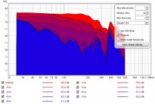
Yes, 1db of power is not much. But diffraction is mostly in the decay (much like the basic 2d sims shows).but if you look the graphs on your results the difference seen in frequency response by dounbling box depth is about 1db or so.


But what happens is the baffle has no control and wabbles for all frequencies lower than 1wl of the z depth. Note how 4400 hz and above are flat for the 3" Z baffle. This is making every angle wabble vs every angle flat based on the depth.
I have only measured this one time so there is that. I will try again in the future. Does anyone else want to stick foam on the back of their speaker?
This. I don't care about tone as long as the ideas are good.we are here to learn
I;ve done some simple tests in the past to change the baffle size:

Changing the size changes the decay.
The baffle is very small and changing the surface of the baffle can also change the decay:

2 diff baffle surfaces:


- Home
- Loudspeakers
- Multi-Way
- Headshake's far field 3way