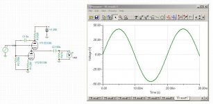
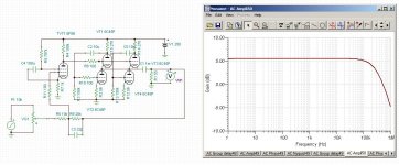
ECC99 putting out 1 watt into 1k ohms @ 0.6% THD. (signal shown is the output across the 1k resistor) Plate resistor is optimized via FFT. Notice that the plate resistor for this one is different than the one for the 6SN7, so it's not just a function of the load but of the AC and DC current in the tubes as well (the ECC99's are running at some 18mA whereas the 6SN7's were running at about 11mA). The formula provided by Mr. Broskie is incorrect. Also, see the Headwize article:
The Morgan Jones Mini Tube Headphone Amplifier | HeadWize
Clearly, Mr. Jones' circuit was not optimized either.
The feedback signal from the plate resistor to the grid of the lower tube is a function of the current flowing through the upper tube. The WF is a normal class A single ended cathode follower with a constant current load that is modulated by a signal from the plate of the upper tube. In reality, the WF is an unbalanced cathodyne circuit wherein the upper signal is fed back to the lower grid. Therefore, the value of the plate resistor determines the amount of feedback to the lower tube and is a function of the current (and therefore the load) flowing through the tube. It is possible to modulate the lower grid from a different source and achieve very good results as well as decouple the embroglio of tying up the optimum plate resistor with the value of the load.
So, it seems that it could be possible to unbalance the cathodyne in the opposite direction as well, to make a gain stage.
Attachments
Last edited:
No it took Mr. Broskie and Mr. Alex Cavalli to fully understand the high value load resistor would produce too much voltage swing for the grid of the bottom tube to get any proper output.
And you are correct, different tubes with different transconductance will determine the optimum load for a large part.
Given schematic could have some GNFB to reduce the THD even further.
EDIT: Your optimum value does decrease THD, but only for small signal levels. Anything above 100mVp and your THD will rise very quickly because the lower grid is driven too hard. Balance the grids for best results.
Last edited:
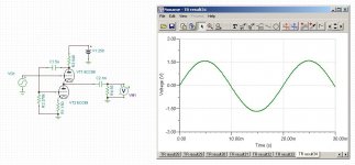
ECC99 driving 55 ohms @ 24.5 mW @ 50 Hz @ 0.34% THD. (signal shown is the output across 55 ohms) That's about the limit , also, which is 3 Vp-p input. Optimum value of plate resistor (lowest THD) remains the same regardless of input voltage. The idea that the grid AC voltages have to be equal for lowest THD does not appear to be correct according to the FFT.
Attachments
Last edited:
I think it's also fairly obvious that if I bypass the cathode resistor of the lower tube, that the gain for that tube increases and thus a different optimum value of plate resistor for the upper tube is required. 3 Volts p-p input, 0.4% THD @ 50 Hz. I think it's also clear that bypassing the lower tube's cathode increases distortion because it increases the gain of the lower tube and obviates the current feedback provided by the unbypassed resistor.
Attachments

Hmm, interesting.
I think I understand what's happening. You are applying NFB to the lower triode's cathode. Although the signal at the grid is bigger than the upper triode, the actual amplified grid-cathode potential isn't. So when omitting the cathode bypass cap you have to take this into account. The grid-cathode voltage is actually about as big as the upper triode's grid signal. So my advice holds in a way. I used LED biasing, that's why 220 is still the optimum value in my case.
EDIT: Ah, crossposting 😀
Last edited:
The value of the optimum plate resistor for LED biasing of the lower tube would be different than either of the arrangements I've shown so far. I don't really like LED biasing, but that's my bias after all....
Sure, to each his own. But I think we've established you can't just calculate the optimum resistor by the simple equation given here and there. There's more to it than that.but that's my bias after all....
But still, the ECC99 WCF makes an awesome output stage for my headphones. I've measured 0.04% THD with an output impedance of 11 ohms with GNFB. Pretty decent I'd say.
Hi,
Prior to the ECC99 I used this circuit for all sorts of applications.
Dirk, if you don't mind, could you run it through the sim?
TA, 😉
Prior to the ECC99 I used this circuit for all sorts of applications.
Dirk, if you don't mind, could you run it through the sim?
TA, 😉
Frank, what is the load for that circuit? (what did you connect it to) It's important because it changes the ideal plate resistor value (that one may not be optimum for the load, for example).
Hi Dirk,
The stage sees an input impedance of 100K at the amp's end.
It's actually the buffer stage of a phono preamp I've done many years ago.
Thanks, 😉
The stage sees an input impedance of 100K at the amp's end.
It's actually the buffer stage of a phono preamp I've done many years ago.
Thanks, 😉
800mVrms into 55 ohms @ 0.02% THD @ 1kHz. You do need a huge coupling capacitor though.
Yes, 470uF works perfect for my intentions. But a 32 ohm Grado might need a little more.
Hi Dirk,
The stage sees an input impedance of 100K at the amp's end.
It's actually the buffer stage of a phono preamp I've done many years ago.
Thanks, 😉
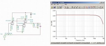
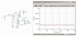
That's a really strange animal. THD @ 1 kHz @ 650 mVrms into the 100k ohm load is 0.001%, whereas if they took the output from the upper tube's cathode the gain would be a little higher and the THD would be 0.0004%. It seems to be a combination of an SRPP and a WF.
Attachments
Last edited:
Hi,
LOL.
I somewhat expected the THD to be lower at the top triode's cathode.
Hope you like it, 😎
Cheers, 😉
That's a really strange animal
LOL.
I somewhat expected the THD to be lower at the top triode's cathode.
Hope you like it, 😎
Cheers, 😉
Sure, to each his own. But I think we've established you can't just calculate the optimum resistor by the simple equation given here and there. There's more to it than that.
But still, the ECC99 WCF makes an awesome output stage for my headphones. I've measured 0.04% THD with an output impedance of 11 ohms with GNFB. Pretty decent I'd say.
Yes, it appears that the plate resistor for the WF has to be empirically determined with the assistance of a THD meter or an FFT analyzer while it's driving the intended load.
If you put a second ECC99 WF in your circuit I'm sure you'd achieve even lower THD.
What's the story on the ECC99 anyway? I can't find any old data sheets on it, only the one from JJ. Did they invent this tube or what?
Hi,
Yes, it is a JJ design. Somewhat similar to the Russian 6N6P but with the same pinout as the 12A*7 series.
They (JJ) also have a 12DW7 with reversed triode layout.
Ciao, 😉
I can't find any old data sheets on it, only the one from JJ. Did they invent this tube or what?
Yes, it is a JJ design. Somewhat similar to the Russian 6N6P but with the same pinout as the 12A*7 series.
They (JJ) also have a 12DW7 with reversed triode layout.
Ciao, 😉
Well, JJ is missing some important data then, like the maximum allowable grid resistor. I assume it's at least 500k or so, but don't know without them telling me. The 12BH7 limit is 1M ohm for self bias, but the ECC99 has higher Gm so maybe a lower grid resistor is called for. Either way, I don't see it in their data sheet.
What's embarrassing is designing and partially buidling a headphone amp for my own headphones where I thought they were 300 ohm but in fact are only 50. But fortunately, saving myself by realizing that I can substitute a JJ ECC99 for the 12BH7 and cut the THD into 50 ohms by about 4 times... so, now I have to buy more tubes!
Hi,
Can't find it either but going by the list of valves the ECC99 can replace (5687,E182cc etc.) (according to JJ) a 1M gridleak can be assumed I guess.
Ciao, 😉
Either way, I don't see it in their data sheet.
Can't find it either but going by the list of valves the ECC99 can replace (5687,E182cc etc.) (according to JJ) a 1M gridleak can be assumed I guess.
Ciao, 😉
- Status
- Not open for further replies.
- Home
- Amplifiers
- Tubes / Valves
- Headphone Impedance and headphone amplifier