Impedance matching gives maximum power transfer. Headphones are sensitive enough that impedance matching may not be required. The IEC standard for a headphone output calls for 120 Ohms source impedance (not that anyone follows it...). If you use a 100 Ohm resistor from a speaker impedance, you'll be close to this, and have 10 dB attenuation with 32 Ohm phones, likely improving the S/N ratio. OTOH, some headphones will sound better with a lower source impedance (improves damping). But it's not "matched" in either case.
Ian,
Which Edcor transformers did you use and what was your impression of them?
Thanks
I used the XSE 10 50 8K type. It is intended for single ended tube circuits but I used it because it has the right turns ratio and roughly the right input and output impedances. It's specified frequency response is 70Hz to 18KHz which is not exactly hi-fi but that is in an SE circuit whilst carrying dc current and driven from a relatively high source impedance. Capacitively coupled (no dc) from the low source impedance of the SRPP with NFB it does rather better, especially at the low end. It is still not a patch on the Sowter but apparently sounds OK. I never actually listened to it myself, I just tried it for a guy who was building the headphones amp and wanted to save some money. I still have that prototype and the two Edcor transformers. They are due to be built into a mixer I am building so I will get to hear them soon.
Cheers
Ian
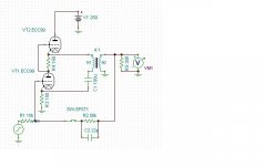
In my 'improved' headphones amp design I use the Sowter 8665 output transformer which has taps that can be configured for headphones from 32 ohms to 600 ohms.
http://www.ianbell.ukfsn.org/EzTubeMixer/docs/headphonesamp/phonesampcctsht1of2.jpeg
I have a couple of spare PCBs for this design, You are welcome to one for the cost of shipping.
Cheers
Ian
Hi Ian, I'm just curious about your design.
Did you consider using a White Follower instead of the SRPP?
Does the feedback network upset the bias on your input tube?
Did you consider taking feedback from the secondary of the transformer?
Hi Ian, I'm just curious about your design.
Did you consider using a White Follower instead of the SRPP?
Does the feedback network upset the bias on your input tube?
Did you consider taking feedback from the secondary of the transformer?
Yes I not only considered, I tried the White follower. I could not get more the 125mW out of it. It's problem is that although it has an incredibly low small signal output impedance , its drive capability is limited.
The feedback network is an integral part of the bias of the input tube. The output of the SRPP sits at about 150V so the 47K feedback resistor provides about 3mA current though the 470 cathode resistor thereby accounting for 1.5V of the input tube bias. The remainder is due to the input tube cathode current.
I did consider taking the NFB from the transformer secondary. However, just about all the distortion occurs in the SRPP stage. Taking NFB from the transformer secondary would only make a very minor improvement in distortion and add a whole bunch of stability issues I preferred to avoid.
Cheers
Ian
Thanks Ian.
The drive capability of the White Follower can be improved substantially by optimizing the plate resistor, however, it will be optimum for only one specific load on the output for the stage.
The drive capability of the White Follower can be improved substantially by optimizing the plate resistor, however, it will be optimum for only one specific load on the output for the stage.
Thanks Ian.
The drive capability of the White Follower can be improved substantially by optimizing the plate resistor, however, it will be optimum for only one specific load on the output for the stage.
Exactly and it is difficult to force an end user to do this. Although the SRPP also has an optimum drive impedance, it is much more tolerant of loads that diifer from the optimum and will still drive a good deal of power into them.
Cheers
Ian
Also, you can substantially lower the output impedance for your amp by taking the feedback from the transformer secondary rather than the primary. It's up to you of course. I would never tell you what to do. I'm doing that with the one I'm building.
Just for fun, here's what can be done with a 6SN7 White Follower. Twenty volts p-p driving 1k ohm. Visual clipping occurs at over 35 V p-p input, which is about 2.3% THD and works out to 21 V rms into 1 k ohm. (441 mWatts) I think that's pretty dang good!
Just for fun, here's what can be done with a 6SN7 White Follower. Twenty volts p-p driving 1k ohm. Visual clipping occurs at over 35 V p-p input, which is about 2.3% THD and works out to 21 V rms into 1 k ohm. (441 mWatts) I think that's pretty dang good!
Attachments

Hi,
The reasoning behind the use of the WCF stage is often misunderstood.
A WCF is great at swinging huge amounts of volts but can't source much current.
IOW, lowest Zout is a meaningless target (within reason) if it can't properly drive the Zin.
Ciao, 😉
The reasoning behind the use of the WCF stage is often misunderstood.
A WCF is great at swinging huge amounts of volts but can't source much current.
IOW, lowest Zout is a meaningless target (within reason) if it can't properly drive the Zin.
Ciao, 😉
My experience, after playing with WCF/SRPP for a while, is that a µ-follower with a mosfet on top is a better solution for headphones, offering low output impedance while preserving the character of the bottom tube. It offers some other advantages on top (no worries about Vhk, less heater supplies, reduced B+ by about 25%, etc) but the very low output impedance might require a rc network in // with the parafeed cap.
But I'll admit that it is an hybrid solution and that, as such, it might not please everyone and I'll stop at that.
But I'll admit that it is an hybrid solution and that, as such, it might not please everyone and I'll stop at that.
I'm working on a Mu-Follower Parafeed headphone amp. I'm using a 71A as the bottom tube for the output and have simulated it with both a 6J9P on top, and a DN2540 on top.
The all tube version shows lower distortion than the hybrid version. I'm curious to see if the actual circuit behaves the same way.
At the present time I can't build it as my tubes are packed up.
The all tube version shows lower distortion than the hybrid version. I'm curious to see if the actual circuit behaves the same way.
At the present time I can't build it as my tubes are packed up.
but the very low output impedance might require a rc network in // with the parafeed cap.
Could you briefly explain this? Is the R/C damping some potential ringing?
I'm building a headphone amp w/ the topology you described.
My experience, after playing with WCF/SRPP for a while, is that a µ-follower with a mosfet on top is a better solution for headphones, offering low output impedance while preserving the character of the bottom tube. It offers some other advantages on top (no worries about Vhk, less heater supplies, reduced B+ by about 25%, etc) but the very low output impedance might require a rc network in // with the parafeed cap.
But I'll admit that it is an hybrid solution and that, as such, it might not please everyone and I'll stop at that.
Did you try cascoding the upper Mosfet in the SRPP? It sims very well.
I just put a 1M ohm resistor in parallel with the parafeed cap. It allows a trickle of current through the output transformer (which shouldn't hurt it too much) and it provides some good damping. I also put the parafeed cap on the low side of the transformer primary.
I'm working on a Mu-Follower Parafeed headphone amp. I'm using a 71A as the bottom tube for the output and have simulated it with both a 6J9P on top, and a DN2540 on top.
The all tube version shows lower distortion than the hybrid version. I'm curious to see if the actual circuit behaves the same way.
At the present time I can't build it as my tubes are packed up.
Did you get more gain with the DN2540 vs. the tube? I would assume you would.
That 71A is a real antique!
It's rather that you could have a serious bump in the low frequencies.
This website explains it in details (go to part3) and provides an excell spreadsheet. It's also quite easy to sim in spice if you have sufficient data about your transformer.
edit: this to answer post 32.
In my sims these resonant peaks don't show up until way down around 1 Hz or less. So, I don't consider them a serious problem.
You can use this connection to reduce distortion in the bass frequencies. It's kind of like an ultrapath connection for the parafeed capacitor.
Oh, and I give up on trying to design something that will drive 32 ohm Grados. I think Grado is an idiot for designing headphones with only a 32 ohm impedance. The hype they promote about it is absurd to me.
Oh, and I give up on trying to design something that will drive 32 ohm Grados. I think Grado is an idiot for designing headphones with only a 32 ohm impedance. The hype they promote about it is absurd to me.
Attachments
Last edited:
In my sims these resonant peaks don't show up until way down around 1 Hz or less. So, I don't consider them a serious problem.
It's highly dependant on the setup of course (particularly your transformer). In a prototype setup, I had a peak of 6db at 25hz. But output impedance was near 0 (4ohms), my output cap was much smaller and I was using recycled 100V line transformer with lowish inductance.
Increasing any of these will reduce the problem.
Did you try cascoding the upper Mosfet in the SRPP? It sims very well.
I just put a 1M ohm resistor in parallel with the parafeed cap. It allows a trickle of current through the output transformer (which shouldn't hurt it too much) and it provides some good damping. I also put the parafeed cap on the low side of the transformer primary.
No, I didn't try it. I might in the future. The upper mosfet is a IRF710 with fixed bias btw. I've to find the motivation though... I must admit I'm not using the amp in parafeed mode much. Taking the output directly from the output capacitor, I've measured distortion as low as 0.028% (@1Khz, 0.7Vrms into 300r which is a comfortable average output for the hd650). That's open-loop.
Last edited:
Yeah, I consider 100uF to be the minimum parafeed capacitor value. Sometimes, larger is better. I suppose that's one of the downsides of the parafeed arrangement.
You got good performance for open loop! Bravo.
You got good performance for open loop! Bravo.
I've just been looking at my sims and was seeing the resonance aboce -f3 as well. I realized it is the LC resonance of the output cap value and transformer inductance. The lower the transformer resistance the worse the peak will be (high Q circuit).
It appears to me that the only option is to push the resosnace frequency well below the desired -f3 point.
So the capacitor value is totally dependant on the inductance of your transformer.
In my case with a 10H transformer I need at least 80uF. This puts the peak below 10Hz
It appears to me that the only option is to push the resosnace frequency well below the desired -f3 point.
So the capacitor value is totally dependant on the inductance of your transformer.
In my case with a 10H transformer I need at least 80uF. This puts the peak below 10Hz
- Status
- Not open for further replies.
- Home
- Amplifiers
- Tubes / Valves
- Headphone Impedance and headphone amplifier