This was the third headphones amplifier I made mabe 10 years ago with drv134.It was cool at the time and probably still is.This one, which I designed, is super-simple and has been cloned multiple times. https://www.diyaudio.com/community/...amp-using-that1646.163544/page-2#post-5233570

Circling back here... @steveu is right - what I care about most is reliable, solid headphone drive/power/volume at stage levels, not the few tenths of a percent of THD. I also value simplicity in the design, as it's possible that I could make more than a few of these.
That being said, I'm happy to include output driver structures that include additional heavy duty transistors or LME49600s or whatever if it improves the design appreciably, but I don't think I want to go to split rails. Another of my design goals is keeping this thing small. So far it all fits in a 2.5x4.5 hammond aluminum box, including all connectors and pots. Here's a picture of it compared with a commercial unit that has two less inputs and is much larger. (and most importantly, doesn't fit on my pedalboard, hence my this new design.)

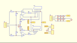
Here's my design as currently implemented, including modifications. (modifications are in red)


So far it generally works well. I have tested with a few different sets of headphones and in-ears. The ones that give me the most trouble are my UE RR set. According to UE, they have about a 35Ohm impedance, but their sensitivity must be a bit low too, as I can't quite get them as loud as my other in-ears or the beyer DT770 cans I have. There's also a bit of fuzz in when I play loud into the UEs that I don't hear in the other headphones.
I'd like to increase the available volume from this unit. Any thoughts on that? Is is just a matter of increasing the gains of each input (have already doubled most of them as you can see.) If so, are there practical limits as to how low I can take the input resistors?
In a future PCB, I might opt to add an intermediate mixing stage and or/gain stage, but on this board I'm not going to do that, as the modifications would be too extensive.
Thanks all!
Geoff
That being said, I'm happy to include output driver structures that include additional heavy duty transistors or LME49600s or whatever if it improves the design appreciably, but I don't think I want to go to split rails. Another of my design goals is keeping this thing small. So far it all fits in a 2.5x4.5 hammond aluminum box, including all connectors and pots. Here's a picture of it compared with a commercial unit that has two less inputs and is much larger. (and most importantly, doesn't fit on my pedalboard, hence my this new design.)
Here's my design as currently implemented, including modifications. (modifications are in red)
So far it generally works well. I have tested with a few different sets of headphones and in-ears. The ones that give me the most trouble are my UE RR set. According to UE, they have about a 35Ohm impedance, but their sensitivity must be a bit low too, as I can't quite get them as loud as my other in-ears or the beyer DT770 cans I have. There's also a bit of fuzz in when I play loud into the UEs that I don't hear in the other headphones.
I'd like to increase the available volume from this unit. Any thoughts on that? Is is just a matter of increasing the gains of each input (have already doubled most of them as you can see.) If so, are there practical limits as to how low I can take the input resistors?
In a future PCB, I might opt to add an intermediate mixing stage and or/gain stage, but on this board I'm not going to do that, as the modifications would be too extensive.
Thanks all!
Geoff
really? at 35 ohms and a P-P output signal at half my supply, I should be able to push almost half a watt, right? which ought to be enough to blast my eardurms off with any set of headphones, I'd imagine, especially in-ears.
P = (V*V)/Z = (4.5*4.5)*0.707/35 = 0.4W
* 0.707 because Vrms vs Vp-p
P = (V*V)/Z = (4.5*4.5)*0.707/35 = 0.4W
* 0.707 because Vrms vs Vp-p
Happy to swap opamps, that's an easy fix. I do have an OPA1656 I could use.
Here's how close the 4580 can get to the rail according to the datasheet. It still seems like I ought be to able to generate something hefty enough with a single 9V supply, but I can't argue with the results. just doesn't quite make sense to me.

Here's how close the 4580 can get to the rail according to the datasheet. It still seems like I ought be to able to generate something hefty enough with a single 9V supply, but I can't argue with the results. just doesn't quite make sense to me.
Ah, gotcha! Thanks, i'll look for that. probably explains the hair I hear on the signal too 🙃Max output current(100mA)is your limit. OPA1656 has the same limit. Search for 200 a 250mA opamp.
Nice trick. just a follower that adds additional current through the summing resistors. probably a more intense modification than I'd like for this board, but we'll see.
First step is to look for a heftier output opamp
First step is to look for a heftier output opamp
One additional question. I gather that the 10ohm resistors are there to limit the output current of the headphone driver amp under short circuit conditions, and maybe to introduce some small amount of stability.
Is there any reason not to put them inside the feedback loop?
Is there any reason not to put them inside the feedback loop?
Looks like a great part, that ought to be enough juice to drive anything I can connect to it!LT1210, one of the best. 🙂
It'll have to be for a different project, or future version of this project though, as it's a to220 package, and I'm limited to SO-8s on this board. 🙃 Also looks like it likes dual supplies, which I haven't quite broken the seal on yet.
Well, I ordered an AD8397 to try out; it's supposed to have ~230mA of AC output current capability according to the datasheet, and gets close to the rails even at high output current, so hopefully this will be an improvement.
Relatively expensive little opamp, though, $7 at digikey 🙃
Relatively expensive little opamp, though, $7 at digikey 🙃
haha could have tried this one too, looks like a gooc choice. maybe I saved myself a dollar though!
I borrowed a Behringer P2 from a friend and had a peek inside. It's a pretty commonly used IEM driver designed for wired use. It runs on 2 x AAA batteries, not sure of the runtime. I've used them before, and they work fine, and sound fine. As someone mentioned, my and the Behringer P2 goals aren't vanishingly small THD, but solid, loud performance and utility.
Notable findings are:
1. They use an LM2662 switched capacitor IC to generate a mirror negative supply from the ~3V generated by the battery. According to the datasheet, this little guy is capable of supplying 200mA, which ought to be more than enough for their (or my) needs.
2. They use an LM4808 headphone driver IC. It's designed for low voltage operation, max Vcc-Vee = 6V
3. There are a couple of TP1516 dual op amps used as well. I'm not sure what they need with four whole opamps besides the headphone driver, for a single stereo input, but they're there.
All this has me thinking, if a bare-bones, cheap-ish commercial headphone driver can do a split supply, maybe I should think about it too??
Anyone have thoughts on the pros/cons of AC coupled designs vs the complexity of building a split supply?
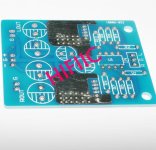
I bought that very PCB on ebay. what changes did you make? Any problems with DC offset since there is no DC servo?Sorry guys, this one is simple(2Watt a channel) and used for DJing.
Super low distortion, see “the wire” thread.
View attachment 1233257
Attachments

- Home
- Amplifiers
- Headphone Systems
- headphone driver reference schematics