This is also an interesting project. There is a PCB to buy which simplifies things considerably. Everything is on that PCB, the power supply and the amplifier.
https://guides.diyaudio.com/Guide/WHAMMY+headphone+amplifier/3?lang=en
https://diyaudiostore.com/products/whammy-pcb
I suggest OPA1656 or MUSES 02 instead of OPA2604 (obsolete part). Muses is really good. C26 and C27 increase to 100-220uF 10-16V
https://guides.diyaudio.com/Guide/WHAMMY+headphone+amplifier/3?lang=en
https://diyaudiostore.com/products/whammy-pcb
I suggest OPA1656 or MUSES 02 instead of OPA2604 (obsolete part). Muses is really good. C26 and C27 increase to 100-220uF 10-16V
Last edited:
Sigh... Such frustrating reading!
With 1mW as a benchmark, we can look at a typical 32 ohm and use Ohm's law to figure out what we actually need:
√32÷√1000 = 0.178V swing
0.178V / 32 Ohm = 5.59mA
Going the other way to verify:
0.00559A × 0.178V = 0.001W
That's not a lot. Even 16 Ohms with its heavy current requirements could theoretically use an output stage with 2 to 4 × J113's in parallel, using tiny TO-92 components, or SOT-23 surface mount versions:
√16÷√1000 = 0.126V swing
0.126V / 16 Ohm = 0.0079A
Going the other way to verify:
0.0079A × 0.126V = 0.001W (minus all the rounding errors)
What about 600 Ohm?:
√600÷√1000 = 0.775V (a bit more voltage, but still not a lot)
0.77459÷600 = 1.29mA
So the most demanding, "hard to drive" HPs could run on an output stage based on a single JFET and a tiny, very civilised, class-A bias in the single-digit mA range!
I understand that there may be advantages like thermal stability when using a large TO-220 device that is 100x over-powered. But this seems highly inelegant, and the gains may well be outweighed by worse linearity and/or gate capacitance.
If we decide early on to use a nice, linear output stage, the case for an op-amp as a "gain engine" is significantly reduced.
I'd be looking for a sub-miniature circuit using 2 × 9V NiMH batteries, which give a convenient dual supply, eliminating any need for electrolytic output capacitors (which tend to leak current, producing a DC offset anyway).
One circuit that caught my eye recently is the "Caprio" v2 from here:
Art of Electronics X-Chapters BJT amplifier distortion PDF
It would have to be "massaged" a little bit:
4 × 9V batteries could work, but who does that? Maybe 2 × 9V with some adjustments or source a small battery pack.
Maybe use JFETs on the input, taking a inspiration from Pass' 2022 DIY front end.
The Caprio circuit only takes a very light load, but I think it could be solidified to HP levels.
This approach would be a lot of homework though.

Yeah, you're right. I was just lazily counting DC values. The scale doesn't change much though.
BTW ^^ an Edit for the above: the circuit version I had in mind was "Caprio's Quad" v2. It's at the end of the paper, but the whole thing is worth a read.
BTW ^^ an Edit for the above: the circuit version I had in mind was "Caprio's Quad" v2. It's at the end of the paper, but the whole thing is worth a read.
Last edited:
Modern( post 1986) op amps datasheet usually give a chart that shows 40...100mA output current capability with a 1...4 v loss from the V+- supply lines and they also show the best distortion figures at +-15 supply on 600 ohms loads, but many of the most modern ultralow distortion ones allow +-2.5v with inaudible distortions when they need to output a full 1V output.What I didn't see yet in a datasheet, is a very empirical yet predictable SOA figure for the output stage of an op amp.If an op amp can deliver 12..13V rms into 600 ohms resistive load with 0.0001% thd, it can also deliver 50mA into 240 ohms according to available output voltage/current(SOA) graphs in a datasheet , then it should be able to deliver 1.2V on a resistive 60 ohms load with maybe 0.01... 0.001% thd when supplied close to +-5V due to maybe Early effect so just adding a 33 ohms output resistor to a lm4562 or opa2132 like op amp supplied at +-5V allows at least 0.01% thd on real 32 ohms dynamic cans, but trying to avoid Early effect below 5V CE would give a theoretical ideal supply of +-8V , an output series resistor of 150 ohms and maybe 0.01...0.005 % thd on real 32 ohm cans. While I'd just use +-5V supply and go with 33 ohms series output resistor and accept 0.01% thd in 32 ohms cans that can't even reproduce 50Hz with less than 0.2% thd.CMOY amp isn't outhere for nothing.
Last edited:
Indeed. And bearing in mind that we're 99.9% certain to be talking about inductive moving-coil type speakers for the HPs, adding some series resistance is likely to be a good thing in its own right. Output inductors could also be used, maintaining a low impedance in the bass, while raising it at high frequencies. But as usual, EQ will be needed.
If the inductor produces a cut-off at say, 1kHz, significantly more gain will be required at higher frequencies to make the response flat again. So a starting level of 0.0001%THD would be handy.
It would be an interesting experiment to find out where the break-even point is: at what point exactly is the reduced distortion in the HPs counter-balanced by the rising distortion in the amplifier?
We live in a different century now. and technology moved on. Forty years ago, DeLorean was a futuristic looking car, and Studer A810 was a state-of-the-art reel-to-reel audio recording machine with 63dB SNR and 0.5% distortion:
View attachment 1233006
View attachment 1233004
You can still enjoy both DeLorean and Studer, but state of the art is very different these days. Audio gear with 120dB SNR and less than 0.0005% distortion is inexpensive and easily available - that's 60dB, or one thousand times, better than Studer's. And yes, it does sound better (although not necessarily a thousand times better).
W.r.t. Omicron, you completely miss the point. It's not about Class A or B or AB. The Omicron thread shows measurements where the output stage leaves class A, and it is still 10,000 times more linear than the Studer. Omicron's ultra-high performance is due not to its 50mA of quiescent current, but to its sophisticated high-order contol loop and ultra-high loop gain, equivalent to a 700MHz Gain-Bandwidth Product. BTW, that control loop is one example of new technology developed since the times of DeLorean.
I imagine that if you attenuate the output as in your example of a modern high-performance headphone amp, you push any distortion components (ie, harmonics) into the noise floor. Maybe I'm missing something here, but I don't think this is the same as notching out the fundamental. Why not just show the plot as dBr 5V RMS output?
I use a 101:1 attenuator (100 Ohms and 1 Ohm divider) on the front end of my QA401 to test my high power designs and I enter the input attenuator value and the software takes care of the scaling etc to ensure the
No offense meant - please feel free to correct me if I'm wrong.
🙂
Briefly revisiting thermal issues:
With S.E. class A with some kind of current source, the main output device typically (softly) switches current between itself and the load.
To reduce temperature variation, a dual device could be used, either in a bridged configuration (unlikely because most HPs have 3 exposed connections, not 4), or push-pull. So as the 'N' device heats up, the 'P' device cools down with near perfect symmetry.
With power amplifiers the idle current can be much lower than the peaks, so a new problem arises: the power rails get flooded with harmonics. And with a battery we want to avoid that, too. For a small, low-powered battery system, rather than using a huge bias current, an alternative would be that the HPs should have 4 lines*. So that we can use an LTP: a CCS for the tail, and dual devices running bridged.
*It might be possible to still use the common return in the typical 3-wire configuration, but I'm not sure. It's certainly inflexible.
The only problem is that, with very few exceptions like @audioholics, those who can make these measurement on a widely recognized AP equipment worth 12000$ as new would distort the truth and cover partial measurements so that they can still sell snake oil based on having an AP backing them.They didn't buy a damn AP to help the masses! I have first hand experience working with such people as I measured myself the BS they sold later for solid 4 figures $.at what point exactly is the reduced distortion in the HPs counter-balanced by the rising distortion in the amplifier?
What I don't really like is when highly regarded engineers who know and measured the truth by themselves choose to cover all the inconvenience and praise unnecessary technology.They can do it in a marketing commercial environement and I have absolutely nothing against it becsuse vanity has its price and wealth distribution is fair in my opinion. Promoting the same thing in a diy environment...please don't!
In a way it is in our nature to think that the most expensive solutions are necessarily the best, but think of a washing maschine! A washing machine in 1930's wouldn't probably be as good as one made today although having one in 1930 was a real luxury.Today's cheapest 5...7kg washing machine can do a much better job and anyone can have one for cheap.Now if all the washing machines manufacturers would stop making a 5kg one and only sell 15...30kg ones as household appliances telling people that a 5kg wm is pure garbage, the 15kg wm would wash 5kg laundry in the same amount of time with higher electricity waste, in a bigger space and would achieve the same thing as the 5kg w.m.That is exactly what a class A 5kg headphones amplifier does to 32 ohms normal headphones.Less than 0.0001% of the headphones sold in the world are power hungry 86db sensitivity 28 ohms Hifiman headphones...
Most of those who buy 20 000$ electrostatics never even tried 30...200$ headphones made for modest recording engineers simply because it's well under their social status...They pay 200$ for a pair of socks, 5000$ for a wrist watch, how would they be able to buy high end audio equipment for under 100$? That's absolutely insane by their standards of living.Knowing headphones that sells for 300$ using 1$ chinese made drivers, 3000$ headphones using 200$ drivers made in Ukraine and 20 000$ headphones made with less than 1000 investment per unit, I kinda know this sport, but I simply don't like highly regarded engineers that distort and hide the truth simply because they can and their knowledge needs to be sold for big bucks. Of course, that can be argued in What Hifi or other magazines, but on diy forums truth needs to be told.
When I see 80$ Burson V6 adverts here it makes me both laugh and nervous cause it is very unfair advert when opposed to a single op amp in terms of pure power.
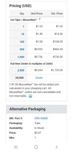
RME ADI-2 is using 3 paralleled opa1688 per channel in a space that's less than 1/3rd of what Burson V6 takes and I can bet any sum of money that no Burson can equal their performance under any circumstance because each of them can handle 70mA at 10 V output or a total of 200mA at 10Voutput per channel! Can Burson V6 at 80$ do it? I doubt that .Let's see the cost of 10 opa1688! Well it's 14$ at Mouser! 5 opa1688 paralleled per channel , 350mA output capability with ultralow distortions for 14$, can your fancy class A hpa beat it? I and a few thousands mastering engineers doubt that..
Attachments
Last edited:
Naturally, for those measurements only the fundamental is attenuated. The distortion products are preserved.Maybe I'm missing something here
I use it with AKG K7XX, Beyer dynamic DT770 pro and Sennheiser HD25 limited edition.
https://www.ebay.co.uk/itm/18611198...MI1e-lp-O5ggMV3aKDBx3JPg6mEAQYGSABEgK0C_D_BwE
Last edited:
The only problem is that, with very few exceptions like @audioholics, those who can make these measurement on a widely recognized AP equipment worth 12000$ as new would distort the truth and cover partial measurements so that they can still sell snake oil based on having an AP backing them.They didn't buy a damn AP to help the masses! I have first hand experience working with such people as I measured myself the BS they sold later for solid 4 figures $.
What I don't really like is when highly regarded engineers who know and measured the truth by themselves choose to cover all the inconvenience and praise unnecessary technology.They can do it in a marketing commercial environement and I have absolutely nothing against it becsuse vanity has its price and wealth distribution is fair in my opinion. Promoting the same thing in a diy environment...please don't!
In a way it is in our nature to think that the most expensive solutions are necessarily the best, but think of a washing maschine! A washing machine in 1930's wouldn't probably be as good as one made today although having one in 1930 was a real luxury.Today's cheapest 5...7kg washing machine can do a much better job and anyone can have one for cheap.Now if all the washing machines manufacturers would stop making a 5kg one and only sell 15...30kg ones as household appliances telling people that a 5kg wm is pure garbage, the 15kg wm would wash 5kg laundry in the same amount of time with higher electricity waste, in a bigger space and would achieve the same thing as the 5kg w.m.That is exactly what a class A 5kg headphones amplifier does to 32 ohms normal headphones.Less than 0.0001% of the headphones sold in the world are power hungry 86db sensitivity 28 ohms Hifiman headphones...
Most of those who buy 20 000$ electrostatics never even tried 30...200$ headphones made for modest recording engineers simply because it's well under their social status...They pay 200$ for a pair of socks, 5000$ for a wrist watch, how would they be able to buy high end audio equipment for under 100$? That's absolutely insane by their standards of living.Knowing headphones that sells for 300$ using 1$ chinese made drivers, 3000$ headphones using 200$ drivers made in Ukraine and 20 000$ headphones made with less than 1000 investment per unit, I kinda know this sport, but I simply don't like highly regarded engineers that distort and hide the truth simply because they can and their knowledge needs to be sold for big bucks. Of course, that can be argued in What Hifi or other magazines, but on diy forums truth needs to be told.
When I see 80$ Burson V6 adverts here it makes me both laugh and nervous cause it is very unfair advert when opposed to a single op amp in terms of pure power.
RME ADI-2 is using 3 paralleled opa1688 per channel in a space that's less than 1/3rd of what Burson V6 takes and I can bet any sum of money that no Burson can equal their performance under any circumstance because each of them can handle 70mA at 10 V output or a total of 200mA at 10Voutput per channel! Can Burson V6 at 80$ do it? I doubt that .Let's see the cost of 10 opa1688! Well it's 14$ at Mouser! 5 opa1688 paralleled per channel , 350mA output capability with ultralow distortions for 14$, can your fancy class A hpa beat it? I and a few thousands mastering engineers doubt that..
For personal use and with minimal pretentions to "going pro" in audio, I would focus on subjective impressions rather than overkill with OTS test equipment. The whole "measuring to find out if it's 0.01% or 0.002%" bores me, especially with the sort of confounding cases with 2 competing sources of distortion. Even if we could look at the spectrum it still may not be obvious which one ought to be better from a technical standpoint.
For instance, 2 different HD spectra that both add up to exactly 0.003%THD. My blind guess would be that the one where the H2 and H3 are more dominant, would sound subjectively better, partly because of hearing frequencies logarithmically. For one thing there is a much bigger "distance" between H1 : H2 : H3 than say, H7 : H8 : H9. The higher ones tend to be more dissonant. But also, there's the Fletcher-Munsen curves, which mean the measurements should actually be weighed to take into account the 20-40dB higher hearing sensitivity in the typical 4kHz "scream" region. In that sense, the "audiophile" lore of not caring so much about THD, so long as it's mostly H2 makes sense.
I also stumbled upon 2 different ways of measuring THD a while ago: either with or without adjustment for phase shifts. It occurred to me that some interesting (or annoying) effects were possible, such as narrow high-voltage spikes, which add up to almost nothing THD-wise, but because of the very low area under the curve, they could be subjectively fatiguing. One explanation could be the HF energy puts physical pressure on the ear drum and might induce some internal distortion in the ear. Yet if the phases are shifted, the same energy merely produces some tiny insignificant 'grit' on top of the signal.
@abstract about a decade ago I talked with a guy who used to fix only high end gear in a very specialized Munich repair center and he said that the best and most expensive amplifiers almost always showed H2 and H3 with everything else under the noise treshold of the measuring equipment and it makes sense in your light to have only consonant harmonics covering for everything else. I've seen similar photos on a few japanese sites also with some of the very best amps they made where they use some Panasonic VP to show off...same thing : very low H2 and H3 and nothing else that you can read on the screen.No measurable distortion at all , no audible distortion or pleasant distortion all have their place in the larger room, I only care about the effort and costs if it's for my own use.Proving which one is better is just a lot of trashtalk these days...It all depends on ones ears...
The OP needs to drive headphones for queuing in a noisy club where the ambient sound level is maybe 110dBA. He does not care about < 0.01%THD and he needs to push the headphones to their power limit. You may love listening to fine recorded music in your quiet home, but that is nothing like what is needed here.
This one, which I designed, is super-simple and has been cloned multiple times. https://www.diyaudio.com/community/...amp-using-that1646.163544/page-2#post-5233570
- Home
- Amplifiers
- Headphone Systems
- headphone driver reference schematics