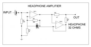
Here is a very interesting circuit for a headphone amp.
The bias for the output is controlled so that all of the output transistors remain on all of the time, thereby eliminating crossover distortion. The workings are explained in this article:
http://www.edn.com/contents/images/6702272.pdf
Hat tip to Bigun for this one.
The bias for the output is controlled so that all of the output transistors remain on all of the time, thereby eliminating crossover distortion. The workings are explained in this article:
http://www.edn.com/contents/images/6702272.pdf
Hat tip to Bigun for this one.
Attachments
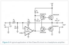
The circuit in post #1 is basically a method for paralleling a buffer with an amplifier, but it has little to do with the bias.Here is a very interesting circuit for a headphone amp.
The bias for the output is controlled so that all of the output transistors remain on all of the time, thereby eliminating crossover distortion. The workings are explained in this article:
http://www.edn.com/contents/images/6702272.pdf
Hat tip to Bigun for this one.
Also note that not all amplifiers will tolerate the additional phase shift.
Regarding this one http://www.edn.com/contents/images/6702272.pdf, it is instructive to look at J Broskie comments about it (bottom of the page):
http://www.tubecad.com/2010/04/blog0186.htm
What is the impedance of your headphones?
As hinted by the circuits above, you need some extra grunt to properly power lower impedance headphones to full volume (<250 ohm). Common op-amps do not do a good job by themselves.
Many popular headphone amps are based on this:
http://waltjung.org/PDFs/WTnT_Op_Amp_Audio_2.pdf
It is a diamond buffer done with discrete components. Many common transistors can be used 2N4401/3, 2N3904/6 etc.
See part 1 for where the buffer fits into the op-amp circuit:
http://waltjung.org/PDFs/WTnT_Op_Amp_Audio_1.pdf
The headphone can be 32 ohm also.
Awiaitng comments on about circuit.
or
how about using single OPA 2134 for both the channels without buffer stage.
Awiaitng comments on about circuit.
or
how about using single OPA 2134 for both the channels without buffer stage.
Try this.
If you have plenty of 5532's, then you can easily build a nice little HP amp with 60-80mA of drive which should be fine to drive a 32 Ohm set of 'phones.
Also, if you look at my website, I built and measured a very simple class
A HP amp that acheived great results.
If you have plenty of 5532's, then you can easily build a nice little HP amp with 60-80mA of drive which should be fine to drive a 32 Ohm set of 'phones.
Also, if you look at my website, I built and measured a very simple class
A HP amp that acheived great results.
Attachments
Scale Doug Self's paralleled 5532 poweramp down a little according to the impedance of your phones.
http://www.diyaudio.com/forums/chip-amps/174540-doug-selfs-ne5532-power-amp-thoughts-anyone.html
http://www.diyaudio.com/forums/chip-amps/174540-doug-selfs-ne5532-power-amp-thoughts-anyone.html
Hello,
This TI circuit http://www.ti.com/lit/an/sboa031/sboa031.pdf is simple easy and cheap sounds ok too.
I built one using 5532’s.
Same curcuit as yours is on the TI site as an application note! it works!
DT
All just for fun!
This TI circuit http://www.ti.com/lit/an/sboa031/sboa031.pdf is simple easy and cheap sounds ok too.
I built one using 5532’s.
Same curcuit as yours is on the TI site as an application note! it works!
DT
All just for fun!
Last edited:
I have a circuit for a headphone amp that I've been using since 1986.
It was design by late Barry Porter and has a current dumping output stage and works well with any phones from 32 - 600 ohms. I'll post the circuit later.
It was design by late Barry Porter and has a current dumping output stage and works well with any phones from 32 - 600 ohms. I'll post the circuit later.
Thanks for input from friends here. DualTriode, abraxalito & Bonsai.
I am waiting for the circuit from msdin.
The circuit of Mr. Bonsai is having 5 opamp in parallel as buffer.
do we need so many to drive 32 ohms load?
As per dual triode just one buffer stage ok.
Herewith attached one more circuit seen at the following post.
http://www.diyaudio.com/forums/head...mittor-follower-headphone-amp.html#post658897
Just one darlington transistor is used.
Kindly comment on this circuit.
which will be better? with 5532 as buffer ( 1st one) or Darlington BJT ( with this post) as output.
Attachments
Like anything this can can become as complex as you wish...
If you just want a simple h/p amp then try the 5532 on its own with perhaps a series output resistor of say 47 to 220 ohms. I cringe when I start seeing hundreds of milliamps current required for a h/p amp.
If you need to parallel for more current then see this,
http://www.intersil.com/data/an/an1111.pdf
Kindly comment on this circuit.
which will be better? with 5532 as buffer ( 1st one) or Darlington BJT ( with this post) as output.
A TO-220 device in a headphone amp? That should really do the job. You could even drive a small speaker with that circuit. Fairly loud as well. 😀
That current source will need a bit of slide rule work to implement. Drives me nuts, that. I've seen too many of them in scholarly articles and text books - kind of a shorthand for a bunch of components. You know the drill - it is left as an exercise for the reader.


Hello,
You want a real buffer? For Op-amp / chip amplifier this is my all time favorite; BUF634 + 4562. http://www.ti.com/lit/an/sboa065/sboa065.pdf
This is the cheap easy reference standard in my book. The slam will kick you in the teeth. The near 0 output impedance is great.
DT
All just for fun!
You want a real buffer? For Op-amp / chip amplifier this is my all time favorite; BUF634 + 4562. http://www.ti.com/lit/an/sboa065/sboa065.pdf
This is the cheap easy reference standard in my book. The slam will kick you in the teeth. The near 0 output impedance is great.
DT
All just for fun!
Last edited:
http://www.diyaudio.com/forums/head...mittor-follower-headphone-amp.html#post658897
Just one darlington transistor is used.
Kindly comment on this circuit.
which will be better? with 5532 as buffer ( 1st one) or Darlington BJT ( with this post) as output.
Just one darlington....but with a 200mA 'black box' current source and a fair sized heat sink to go with both!
Class A for headphones is neat though...
The 5532 is designed to drive a 600ohm load up to 10V, that is around 17mA .
Lets say your design goal is 100mW of power.
This is sufficient to get most headphones really loud with some headroom.
For a 32ohm resistive load that implies a current drive of 55mA.
A single 5532 cannot do that even when shorted to ground.
For a reactive load like headphones you will require even more current to reach 100mW, lets say 92mA with a power factor of 0.6 (just a guess).
Then there is the impedance of the 'phones which is not really 32ohms - it may drop below 32ohms at some frequencies.
Bottom line is you need mulitple 5532s as buffer,
or a real buffer chip like the venerable 634 (if you can find them),
or do it discrete.
One more circuit, with a good write-up, from ESP:
Headphone Amplifier
For a list of headphone power ratings:
HeadWize - Technical Paper: Understanding Headphone Power Requirements by Dennis Bohn
Last edited:
<snip>
Lets say your design goal is 100mW of power.
This is sufficient to get most headphones really loud with some headroom.
For a 32ohm resistive load that implies a current drive of 55mA.
A single 5532 cannot do that even when shorted to ground.
For a reactive load like headphones you will require even more current to reach 100mW, lets say 92mA with a power factor of 0.6 (just a guess).
Then there is the impedance of the 'phones which is not really 32ohms - it may drop below 32ohms at some frequencies.
Bottom line is you need mulitple 5532s as buffer,
or a real buffer chip like the venerable 634 (if you can find them),
or do it discrete.
<snip>
[/URL]
Hello,
I am not sure how “buffer” is used in this thread.
In post 1 and as in the TI Application Note linked in post 8 of this thread the 5532’s are operating in parallel, there is no buffer insight. The two 5532’s in parallel will source 70ma.
Remember the 47R resistors shown in series with the Op-Amps in the circuit when doing the maths.
DT
All just for fun!
You need to think about some kind of current limiting on the TIP41.
My suggestion: go with the 5532 design. You only need 3 packages, its got built in current limiting, its very low distortion and its simple and cost effective!
My suggestion: go with the 5532 design. You only need 3 packages, its got built in current limiting, its very low distortion and its simple and cost effective!
Hello,
The two 5532’s in parallel will source 70ma.
No. The NE5532 typical short circuit current is 38mA. Do not expect clean signal at 35mA....
The second op-amp in post 1 and the app-note is configured as a unity gain buffer, helping the first to drive the load. Agreed it is not buffering the first op-amp as used in those circuits.
Last edited:
Any comments on this TDA2003 High Performance Headphone Amplifier? It was an AudioXpress project article a few years ago.
No. The NE5532 typical short circuit current is 38mA. Do not expect clean signal at 35mA....
...then again the 32 opamp power amp can apparently drive 8ohms to 16W (44mA per chip?).
So YMMV 🙂
The 5532 OpAmplifier, part 1 - ELEKTOR.com | Electronics: Microcontrollers Embedded Audio Digital Analogue Test Measurement
...then again the 32 opamp power amp can apparently drive 8ohms to 16W (44mA per chip?).
So YMMV 🙂
The 5532 OpAmplifier, part 1 - ELEKTOR.com | Electronics: Microcontrollers Embedded Audio Digital Analogue Test Measurement
64 op amps since this is 32 DIL8 packages with 2 op amps each..😉
That is 32mA/op amp.
- Status
- Not open for further replies.
- Home
- Amplifiers
- Solid State
- Headphone amp NE5532