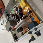
I didn't like the Nichi on the PSU and I changed it for Mundorf...You'll find the difference between both. I think that on this position Dundorf are nice.
For the tantalun... You can use whatever you want. IMO is most critial use the Diode Mod that change this cap.
For the tantalun... You can use whatever you want. IMO is most critial use the Diode Mod that change this cap.
Hello to all,
I read this thread, it contains interesting insights on this circuit and several mods.
I bought a kit of this amp from aliexpress. PCB is of good quality so are the parts provided with the kit.
It works well, but a fact that I noticed is that channels are inverted. I respected the printed labels for R and L channels connections, they are the same I see in many photos of this 3D, but they result on inverted channels.
Could you please check your amps for this issue? Many thanks.
Misprints like that is common on boards nicpom. The silkscreen labelling is done later after circuits are laid out so its easy to overlook these things. Don't worry too much about it and flip it around on the board, they probably noticed it but decided to leave it like that since it doesn't affect performance.
I must disgree, a channel inversion does affect performance a lot, especially if it remains undetected. As these clone PCBs seem very similar, even the silkprint, I wonder how many users have the same problem, and did not noticed it. I would suggest a check of this to all owners of these clones.
When you say the channels are inverted, does that mean the L and R are switched, or one of the channels is out of phase?
- Replace the LM317 voltage setting resistors with zeners (BZX85 13V)
- Replace LM317 C ADj with 10uf 35V Silmics II Black Gold.
İ have 12v 1w zener diodes, can use them for PS filtering you recommend?
I sincerely disagre with your choices...
NCC LZX are incredibly good and neutral sounding capacitors, Panasonic FR are, IMHO, worse here.
FRs are good caps but they sound somewhat 'bigger' than reality and reduces soundstage.
On the opamp, though, higher ESR audio caps give better results, I never tried Pureisms, I've used Silmics II black/gold 100uF 25V.
ERO KP1830 are really good caps but no better than FKP2, the only difference is that KP1830 are a tiny bit more neutral, in this case I would have kept the FKP2.
The polystyrene caps are a good choice but I prefer Amtrans AMCH.
There are two couples of them, I would keep the ones near the opamp, the opamp decoupling on the PCB is really poor (long traces).
Regarding the other two they're used as bypass for the input caps and they're not needed if you use better input caps or can be used to short input caps if you don't need DC blocking.
I don't use input caps at all here, the improvement is stunning.
Absolutely!
Mundorgf AGs are incredible.
BCs are incredibly good for the price but the Mundorf are on another league.
You can also improve the PS with two simple mods:
- Replace the LM317 voltage setting resistors with zeners (BZX85 13V)
- Replace LM317 C ADj with 10uf 35V Silmics II Black Gold.
Also replace all signal resistors with Vishay/Dale RLR07 or PTF56.
I've also used some Vishay VSRJ bulk metal foils but PTF56 will be quite as good.
This modification solved the intermittent power supply noise issue, i think Lehmann Audio should use this simple mod, my clone is dead silent now
Attachments

Has anyone ever tried adding substantial heatsinks to the output devices and increase the bias?
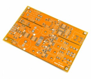

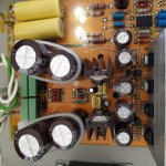
These look very similar but not identical - the orange one has more parts between the filter capacitors and provisions for two different sizes of input coupling cap. Hard to tell which one is better.
From other topics about this amp i have learned that green board have modifications that yellow board doesnt have and its never design but will research more.
Hello!
I have a couple of yellow PCBs kits.
One populated with the parts included as complete kit and another one that I bought bare and have populated myself with upgraded parts from Mouser.
Both sound good but I am inclined to believe that the upgraded 'Mouser board' sounds better.
I have also another PCB (either blue or green-can't remember) coming, so when it comes I will look for any differences.
The yellow PCB is a 'ZeroZone LEM-Copy' and I think it is pretty well made since it has tolerated well with all the soldering/desoldering that took place...
------------
And something for the gurus:
I get a DC offset of around -15mV on the right channel and around -5mV on the left.
This has been pretty constant with several opamps used (OPA2134, LM4562, OPA2227, NE5534, MUSES 8820). The only opamp that resulted in a lower DC offset was the NJM2068. It achieved -11mV right, -1 mV left. Actually, this opamp has been a pleasant surprise regarding its overall performace/price ratio.
Anyway, I 've ordered a couple of 200Ohm trimmer pots for each channel that will go in place of the two 1.1kOhm resistors next to the 100Ohms ones on the board. I'll use them in series with a 1kOhm resistors to adjust the Voltage regulators, in hope of lowering the DC offset.
Is this a valid approach?
It doesn't seem like a bad idea but Have you tried the zener mod on the psu? Maybe this is simple and faster
It doesn't seem like a bad idea but Have you tried the zener mod on the psu? Maybe this is simple and faster
No, I haven't tried it actually.
Would you think they would lower DC offset?
Are the zeners supposed to be used in place of the 1.1kOhm resistors?
I see a few guys doing it, but could never figure out their purpose.
Forgive my ignorance.
Do not worry. Ask what you want. 🙂
Yes, this mod. will help you reduce the offset. It is not the only way but it is one of the simplest and most effective.

Yes, this mod. will help you reduce the offset. It is not the only way but it is one of the simplest and most effective.
Do not worry. Ask what you want. 🙂
Yes, this mod. will help you reduce the offset. It is not the only way but it is one of the simplest and most effective.
Very interesting!
So the original idea with those Zeners was to lower DC offset?
I completely missed that.
Can you recommend particular Zeners for this application?
I'm ready to fill a Mouser order as we speak.
Also, would it be mandatory to use two of them in parallel as it's shown on your photo?
- Home
- Amplifiers
- Headphone Systems
- [Headamp] upgrading a Lehmann BCL clone