Here is a brand new (or supposed so) implementation but one must pay for downloading the schematic. Any clues ?
http://www.elektor.com/magazines/20...ier-with-error-correction-part-1.399028.lynkx
http://www.elektor.com/magazines/20...ier-with-error-correction-part-1.399028.lynkx
steph_tsf said:Here is a brand new (or supposed so) implementation but one must pay for downloading the schematic. Any clues ?
http://www.elektor.com/magazines/20...ier-with-error-correction-part-1.399028.lynkx
Interesting. I wonder if it looks anything like those discussed at length in the permanent error correction thread.
I wonder if it uses BJT or MOSFET outputs?
I wonder what kind of performance is achieved?
Cheers,
Bob
Jakob2 said:I wonder if janneman could help in this case?! 🙂
Jakob2
Well I don't know. They paid me for it, and I guess they want to recoup some of it through on-line sales. If I give out free copies, what would they say next time I submit a design?
Yet, a download cost something like $ 1.80 I think. Not a big obstacle?
Jan Didden
Bob Cordell said:
Interesting. I wonder if it looks anything like those discussed at length in the permanent error correction thread.
I wonder if it uses BJT or MOSFET outputs?
I wonder what kind of performance is achieved?
Cheers,
Bob
YGM
Jan
Originally posted by janneman,
Well I don't know. They paid me for it, and I guess they want to recoup some of it through on-line sales. If I give out free copies, what would they say next time I submit a design? Yet, a download cost something like $ 1.80 I think. Not a big obstacle? Jan Didden
Sorry, it was just meant as a hint for Bob Cordell, who maybe didn´t realize that you was involved.
Jakob2
Hi Jan
From your site
---As far as I know it will appear in the English, Dutch, Spanish and Greek language issues. Feedback, global or not ;-) , appreciated!---
Appeared in french too. I bought it today. I posted a message about it a few days ago on the following forum :
http://www.audax.fr/forum/read.php?4,2431,2438#msg-2438
but I didn't yet know you were the author. I am going to read it just now.
Regards.
forr said:Hi Jan
From your site
---As far as I know it will appear in the English, Dutch, Spanish and Greek language issues. Feedback, global or not ;-) , appreciated!---
Appeared in french too. I bought it today. I posted a message about it a few days ago on the following forum :
http://www.audax.fr/forum/read.php?4,2431,2438#msg-2438
but I didn't yet know you were the author. I am going to read it just now.
Regards.
Yes, I think the languages are wrong. It is what they said to me when I first talked with them (at least what I remember) but apparently it will be in Dutch, German, French and English. I'll change the web site.
Jan Didden
janneman said:
Hello Jan,
I have designed a circuit very similar to yours. While googling "error correction" I ran accross this thread. Since your output stage is very similar I though I would ask your opinion on my circuit.
My goal was to create a very linear class A/B headphone amplifier.
The bias setting diodes would actually be dual series connected silicon rectifier diodes in a TO-220AB package.
http://www.fairchildsemi.com/ds/FF/FFPF60SA60DS.pdf
I still have not settled on what opamp to use, but the simulated opamp actually seems very good fit.
The power devices (MJE15034/35) would be mounted on the same heat sink back to back with the bias diodes using a heatsink like this: http://www.soselectronic.com/?str=371&artnum=S024339.
The cct should have good positive thermal stability. And should have excellent performance even into very low impedance.
Is this sort of thing still considered a form of "error correction?" It seems to me it is a form of error correction, as the opamp makes the output stage more linear to the input stage/VAS.
Any feedback greatly appreciated.
Cheers!
Russ
Attachments
Hello Russ,
Interesting design! I can see similarities to the way I drive the output stage in my paX amp.
It seems to me that the opamp adds gain within a regular feedback loop. Inasmuch as anything with feedback could be considered error correction, this is also a form of it.
Hawksford used a combination of positive and negative feedback in specific ratios to obtain distortion cancellation, which is different from your design, so you could say it is error correction but not Hawksford ec.
That opamp is also interesting, it is actually parts of a current fb opamp combined to get a vfb opamp. A pity that the current output node, where the comp is attached, isn't brought out, then it could have been used as a voltage input current conveyor.
Are you going to build this amp?
Jan Didden
Thanks Jan,
I will probably build it, but I wanted to get a sanity check on it first 🙂 The more confidence I have that it will work, the more likely I am to go for it.
I am actually thing thinking of scaling it up to a power amp too.
All I really need to do is add the driver Qs and the power Qs and add a shunt regulator for the opamp.
Something similar to the attached schematic.
I wonder how it will perform when the output gets to within 6V or so of the rails....
Thanks very much for your time looking at it.
Cheers!
Russ
Attachments
I am simulating halcro here:
http://www.diyaudio.com/forums/solid-state/6362-halcro-amplifier-4.html
hope they won't be angry for the results. Because they said ultra low distortion up to 20kHz full load. My sims result says increased in 10k+hertz and load.
http://www.diyaudio.com/forums/solid-state/6362-halcro-amplifier-4.html
hope they won't be angry for the results. Because they said ultra low distortion up to 20kHz full load. My sims result says increased in 10k+hertz and load.
This could be down to using models in simulators that give results that cannot be proved to be correct.
You may have to build to find why the simulation & models predicted the unreliable results and then use that "real" information to change either the models and/or the simulation.
You may have to build to find why the simulation & models predicted the unreliable results and then use that "real" information to change either the models and/or the simulation.
Hi, Andrew.
Don't worry, I am selecting my transistors models carefully. Iam searcing by goog and found this link* 1st page line2.
There also some real measurements by people, and my sim results still showing better results than real test. It(sim) at least show increasing distortion for HF and load and we know what causing them.
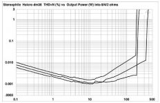
Halcro THD spec is someting hard to achieve in 20khz full load with that topology, or probably halcro distortion spec is coming from simulation results from goodie models or someting.
Link: for goog: halcro distortion measurement result ,, page1 line2
Halcro dm38 power amplifier Measurements | Stereophile.com
Pict from link:
Don't worry, I am selecting my transistors models carefully. Iam searcing by goog and found this link* 1st page line2.
There also some real measurements by people, and my sim results still showing better results than real test. It(sim) at least show increasing distortion for HF and load and we know what causing them.
Halcro THD spec is someting hard to achieve in 20khz full load with that topology, or probably halcro distortion spec is coming from simulation results from goodie models or someting.
Link: for goog: halcro distortion measurement result ,, page1 line2
Halcro dm38 power amplifier Measurements | Stereophile.com
Pict from link:
Attachments
Last edited:
- Status
- Not open for further replies.
- Home
- Amplifiers
- Solid State
- Hawksford output error correction circuit?