Thanks for the compliment Darkfenriz,
In my case it's coming to terms with commercial existence in a country, where when your products are too good/competitive, your family's lives are threatened! Terms of commerce in Australia - at least in High End audio.
ML and Krell were my main competitors - draw your conclusions from that.
Sad, but reality. I have a young family.
Cheers,
Greg
amplifierguru said:
In my case it's coming to terms with commercial existence in a country, where when your products are too good/competitive, your family's lives are threatened! Terms of commerce in Australia - at least in High End audio.
...
Sad, but reality. I have a young family.
...
Sad truly..
However you can consider yourself good father and husband.
Sometimes one must tell secondary from primary issues in life.
That's what makes us humans.
Hope you'll manage to keep your precious family safe and happy and build great amplifiers too.
Keep my fingers crossed.
cheers
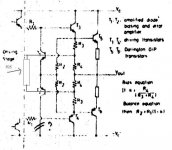
Hi All ! This is a new version ! It is closer to Eltalon .
How can I calculate the value of R1 ?
Thanks !
I can't improve input and vas stage futher . I hope for Hawkford 's circuit .🙂
How can I calculate the value of R1 ?
Thanks !
I can't improve input and vas stage futher . I hope for Hawkford 's circuit .🙂
amplifierguru said:Thanks for the compliment Darkfenriz,
In my case it's coming to terms with commercial existence in a country, where when your products are too good/competitive, your family's lives are threatened! Terms of commerce in Australia - at least in High End audio.
ML and Krell were my main competitors - draw your conclusions from that.
Sad, but reality. I have a young family.
Cheers,
Greg
Amp Guru,
Your amp design looks very interesting. What do you
use for replay system?
Where in Australia are you based?
I'd love to hear your amp!
Cheers,
Terry
I re-simulated Cordell and Eltalon's circuit by orcad pspice . The result is worse than simulating in LTspice
Result is very sensitive with transistors which is used to correct error
if 2 tst error correct is not bc368/bc369 ,result will be worse
a high beta tst such as a872/c1775 can't also better than bc368
I don't know why Halcro 's circuit can kill distortion .I also simulated Halcro's circuit but I don' know any value of error correction circuit 😀 ---> not good , amp has a quite high offset voltage
Is Halcro's circuit beter than Hawksford's circuit ? so what is it ?
Hi Terry Demol,
Thanks. Yes it's a novel design I came up with as an output stage for a chip driven design, which seems so good I decided to give it a life of it's own and am offerring it as a kit for DIY. The chip drive design is also coming along and I hope to launch it as a Hi End Audiophile offerring - as a 150W monoblock suitable in pairs for stereo or 6's, 7's for home theatre. Chassis are being contracted later this week.
I'm in S.E. Qld., Australia.
Cheers,
Greg
A compensation needed?
Hi Hawksford’s gurus!
I need some advise in my last amplifier http://www.diyaudio.com/forums/attachment.php?postid=747297&stamp=1129732489
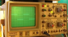
It seems to all work fine, the amp is stable. Bottom I attached 1 kHz square wave test with 6.8 uF with 1 ohm in series at the output.
Regulation of the error correction (EC) is working well by trimming pot R26 (470 ohm). In the range of audio frequency EC is very stable and after adjusting I can not observe any differences between output voltages with 2 ohm and without any resistance at the output of the amplifier.
But with the rising a frequency much more than 30 kHz the correction increasing also and than a voltage without load is slightly greater than with a load. But amp is still stable and all works fine.
Is here a need a frequency compensation for error correction as I see in Cordell paper or Steven design at http://www.diyaudio.com/forums/showthread.php?postid=330446#post330446 as a capacitor from emitters biasing transistors to the ground? If so, what value should I start?
Hi Hawksford’s gurus!
I need some advise in my last amplifier http://www.diyaudio.com/forums/attachment.php?postid=747297&stamp=1129732489
It seems to all work fine, the amp is stable. Bottom I attached 1 kHz square wave test with 6.8 uF with 1 ohm in series at the output.
Regulation of the error correction (EC) is working well by trimming pot R26 (470 ohm). In the range of audio frequency EC is very stable and after adjusting I can not observe any differences between output voltages with 2 ohm and without any resistance at the output of the amplifier.
But with the rising a frequency much more than 30 kHz the correction increasing also and than a voltage without load is slightly greater than with a load. But amp is still stable and all works fine.
Is here a need a frequency compensation for error correction as I see in Cordell paper or Steven design at http://www.diyaudio.com/forums/showthread.php?postid=330446#post330446 as a capacitor from emitters biasing transistors to the ground? If so, what value should I start?
Attachments
Thanks Jorge and Steven, I will try.
Do you think if this really necessary? Why do not have better damping factor for tens and hundreds of kHz?😀
Do you think if this really necessary? Why do not have better damping factor for tens and hundreds of kHz?😀
Steven ! Do you reply my email ?🙂
Hi jarek ! Do you have a tool which can mesure THD ? I dont know its name . Can THD of your amp be zero ?🙂
I adjusted resistors in Hawksford's circuit and distortion seem to be smallest value but this value is still higher than a normal amp .
Perhaps benefit of Hawksford is a high damping factor .
Hi jarek ! Do you have a tool which can mesure THD ? I dont know its name . Can THD of your amp be zero ?🙂
I adjusted resistors in Hawksford's circuit and distortion seem to be smallest value but this value is still higher than a normal amp .
Perhaps benefit of Hawksford is a high damping factor .
Hi Jorge and Steven,
I tried caps (from 22pF to 150pF) from emitters of biasing transistors to the ground but it did not solve the problem. The capacity of 150pF was too much and there was an impact to frequency overall.
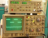
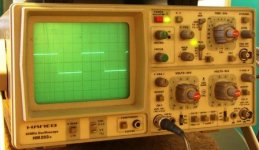
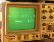
I finished with 180pF capacitors across collectors and bases these transistors and it seems to be a better solution. There is a slight increasing in error correction in the range of 100 kHz to 200kHz. Beyond that, EC is decreasing. I didn’t see any oscillations and amp is very stable. Driving a capacitive loads is not a problem. Up to 100nF no ringing. I have tested the amplifier with different capacitors and 4 ohm resistor at the output.
The first picture:
Signal: sq. 4kHz and 33nF
I tried caps (from 22pF to 150pF) from emitters of biasing transistors to the ground but it did not solve the problem. The capacity of 150pF was too much and there was an impact to frequency overall.
I finished with 180pF capacitors across collectors and bases these transistors and it seems to be a better solution. There is a slight increasing in error correction in the range of 100 kHz to 200kHz. Beyond that, EC is decreasing. I didn’t see any oscillations and amp is very stable. Driving a capacitive loads is not a problem. Up to 100nF no ringing. I have tested the amplifier with different capacitors and 4 ohm resistor at the output.
The first picture:
Signal: sq. 4kHz and 33nF
Attachments
amplifierguru said:You need to explore MOSFETs and savour their seductive advantages!
Steady on old chap!

- Status
- Not open for further replies.
- Home
- Amplifiers
- Solid State
- Hawksford output error correction circuit?