Himaddmaxxdrummer,
The cathodes of the two output tubes are connected to each other, and from there they are connected to a single resistor in parallel with a 50V capacitor that both connect to ground.
I can not read the numbers on that schematic (270 Ohm 2W resistor and 220uF at 50V?) Correct?
That one resistor, and that one bypass cap are a Common self bias circuit (not individual self bias).
To change to individual self bias networks:
Break the connection of the output tubes two cathodes to each other.
Get four 270 Ohm 2 Watt resistors that have very closely matched resistance to each other.
Connect 2 in series (540 Ohm). Connect the other 2 in series (540 Ohm).
Connect one cathode to a self bias resistor: two 270 Ohm 2 Watt in series, to ground.
Connect a 220uF bypass capacitor across the 540 Ohm self bias resistance.
Connect the other cathode to a self bias resistor: two 270 Ohm 2 Watt in series, to ground.
Connect another 220uF 50V bypass capacitor across the 540 Ohm self bias resistance.
Now, each individual output tube cathode sees its own self bias network of 540 Ohm 2 Watt resistor and 220uF cap to ground.
Done.
The current in each output tube is the voltage across its 540 Ohm resistance divided by 540 Ohms.
V/540 = Amps. For example, If the voltage is 16V, the current is 0.0296A (29.6mA).
If the current in the two tubes is badly matched, it would be good to get a few tubes to find a pair that matches (one is either weak, or one is real strong)
Still enjoying my little amp. I was wondering about the this mod above. We changed the shared cathode bias resistor/cap of each pair of power tubes to individual resistor/cap per power tube…
So i saw a video with a guy who has the same amp and had considered this mod but then after some calculations he decided it wasn’t a good idea because it would increase the Milliamp current draw from the power transformer and make it run even hotter than it already does. Your thoughts?
I’ve been using it fine all this time with the mod I was just wondering if this will eventually lead to power transformer failure. Thx
maddmaxxdrum,
Example of a Parallel Single Ended pair of output tubes:
Two tubes cathodes are tied together to a 270 Ohm self bias resistor to ground.
Say the common self bias voltage is 2.7V.
The current is 2.7V / 270 Ohms = 0.010Amp (10mA).
That is an Average current of 5 mA per tube.
270 Ohms x 2 = 540 Ohms
Break the connection between the cathodes from each other.
Now, connect one cathode to a 540 Ohm resistor to ground; and connect the other cathode to a 540 Ohm resistor to ground.
Suppose the self bias voltage on each individual cathode is 2.7V
2.7V / 540 Ohm = 0.050Amp (5mA). 5mA for each tube.
The tubes are well matched, and both dissipate the same plate watts.
But if the tubes are not well matched, one cathode might be at 3V.
3V / 540 Ohm = 0.00555Amp (5.55mA)
And the other cathode might be at 2.4V
2.4V / 540 Ohm = 0.00444A (4.44mA)
5.55mA + 4.44mA = 9.99mA. That is the 10mA current that you had with the 270 Ohm common self bias resistor.
One mismatched tube always was drawing more current than the other, and so it was dissipating more power in the plate, than the lower current tube.
You could not know that with the common self bias resistor of 270 Ohms.
But with individual 540 Ohm self bias resistors you can easily see the un-equal tube currents.
Admittedly, those currents are more like a pair of parallel input tubes.
So, to illustrate a parallel output tube pair, just keep the resistors at 270 Ohm or two 540 Ohm resistors.
. . . But change the self bias voltages to 27V, 30V, and 24Volts, instead of 2.7V, 3.0V, and 2.4V.
The currents are 100mA, (50mA per tube); and 55.5mA and 44.4mA for the unmatched tubes.
Last edited:
maddmaxxdrum,
It has been too long since I read through all 83 posts of this thread; or too many posts to remember even if they only covered one week. So I did not check to see which exact modification you were talking about.
Sorry. I was too lazy.
Please refer to the exact Post #(s).
I only answered your question as a general question, about going from a single common self bias cathode resistor to dividing the currents individually with individual cathode resistors.
Post #s 46 and 55?
If you split the cathodes and connect to individual self bias resistors, you can easily see how well matched (or not well matched) the output tube currents are: bias voltage / self bias resistor Ohms = current, in amps.
And, for anything other than a coupled cathode phase splitter, there most normally would need to be individual bypass capacitors across each individual self bias resisitor.
With no bypass capacitor across an individual self bias resistor, the plate impedance increases, and the gain decreases.
We can get specific, if you mention the Post #(s)
Last edited:
Hi the post was #55.maddmaxxdrum,
It has been too long since I read through all 83 posts of this thread; or too many posts to remember even if they only covered one week. So I did not check to see which exact modification you were talking about.
Sorry. I was too lazy.
Please refer to the exact Post #(s).
I only answered your question as a general question, about going from a single common self bias cathode resistor to dividing the currents individually with individual cathode resistors.
Post #s 46 and 55?
If you split the cathodes and connect to individual self bias resistors, you can easily see how well matched (or not well matched) the output tube currents are: bias voltage / self bias resistor Ohms = current, in amps.
And, for anything other than a coupled cathode phase splitter, there most normally would need to be individual bypass capacitors across each individual self bias resisitor.
With no bypass capacitor across an individual self bias resistor, the plate impedance increases, and the gain decreases.
We can get specific, if you mention the Post #(s)
Thx
Post # 55.
A Parallel Single Ended output stage that has a 270 Ohm self bias resistor with both cathodes tied together . . .
You can use individual self bias resistors of 2 x 270 Ohm = 540 Ohm when you disconnect the 2 cathodes from each other.
The tube currents will tend to be more equal with individual 540 Ohm self bias resistors, one tube can not as easily hog most of the current. Current hogging can easily happen with the cathodes tied together, especially if the 2 tubes are not very well matched.
However, with the common 270 Ohm self bias resistor, a bypass cap is optional, and often best left out.
But with individual 540 Ohm self bias resistors, you should put an individual bypass cap across each 540 Ohm resistor.
I hope that makes it clear.
ThxPost # 55.
A Parallel Single Ended output stage that has a 270 Ohm self bias resistor with both cathodes tied together . . .
You can use individual self bias resistors of 2 x 270 Ohm = 540 Ohm when you disconnect the 2 cathodes from each other.
The tube currents will tend to be more equal with individual 540 Ohm self bias resistors, one tube can not as easily hog most of the current. Current hogging can easily happen with the cathodes tied together, especially if the 2 tubes are not very well matched.
However, with the common 270 Ohm self bias resistor, a bypass cap is optional, and often best left out.
But with individual 540 Ohm self bias resistors, you should put an individual bypass cap across each 540 Ohm resistor.
I hope that makes it clear.
we
If I do his mod, does it interfere with your mod?
Thx
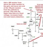
hi hope all is well. I’m still working on this amp.. I was going over the mod u explained to me about making the plate to cathode voltages the same for both triodes of the 6SN7. It’s up in your post quoted above… i saw someone else do another mod to the same amp that makes the lower triode work more resulting in less distortion at higher volumes. He explains it in this video…Your schematics in Posts # 17, 45, 47, and 66 all have the input Cascode triode connections the same.
I am guessing that you like the Cascode circuit topology, better than other input circuit topologies.
If you want to make the plate to cathode voltages nearly the same, then . . .
Disconnect Pin 6 from Pin 2.
Connect a parallel network of 2.2k and 100uF between pin6 and pin2 (cap plus to pin6).
Connect the 1 Meg that Used to connect to Both pins 2 and 6, and connect it only to pin 2.
That will divide the plate to cathode voltages to be about the same on the two input triodes.
Try it and see if it works well for you.
Note: I can not see what the "fascination" nor the advantage is for using a pair of medium u triode tubes in Cascode circuit topology for audio amplifiers.
Perhaps an aggressive marketeer sold us a bill of goods.
Generally, the advantages of using a Cascode circuit at RF, goes completely away when used for Audio.
The RF Cascode circuits are used for very small signals, very low bandwidth circuits (bandwidth relative to the center frequency) and the signal voltages of the RF signals are very small.
Compared to the small RF voltages . . .
That small of an audio voltage is not nearly enough to drive an audio output stage.
Generally, using Cascode circuit to drive the output stage will have low dynamic range, high distortion, and depending on the high frequency load that the output stage presents, will result in high frequency roll off.
Parallel output tubes have 2x the Miller Effect capacitance, and can be just the thing that loads the Cascode too much at high frequencies.
With a single input triode, a resistive plate load, plenty of B+ voltage, and a self biased cathode with bypass cap, it is enough to drive a pair of parallel output tubes. Even without the IXYS current source as the plate load, the resistive plate load gave the gain, linearity, and voltage swing that is needed. The 6SN7 is a good example of a tube that works well there.
I remember a single 6SN7 triode that drove the famous Western Electric 212E triode. That 212E had 1250V on its plate.
That experience got me started designing and building vacuum tube amps again.
Just my opinions.
Sometimes simpler is better.
"You should make things as simple as possible, but no simpler" - Albert Einstein
If I do his mod, does it interfere with your mod?
Thx
Attachments
You are talking about the input stage cascode amplifier, right?
My advice is to do one mod, or to do the other mod, do not do both.
Both mods are intended to set the top triode's cathode voltage (or the bottom triode's plate voltage, depending on how you look at it).
In other words, do not connect a motor output to a Ford transmission input, and then connect the Ford transmission output to a Chevrolet transmission input.
Just my opinions.

Yes, input stage cascode amp. Ok so they do the same thing? ThxYou are talking about the input stage cascode amplifier, right?
My advice is to do one mod, or to do the other mod, do not do both.
Both mods are intended to set the top triode's cathode voltage (or the bottom triode's plate voltage, depending on how you look at it).
In other words, do not connect a motor output to a Ford transmission input, and then connect the Ford transmission output to a Chevrolet transmission input.
Just my opinions.
I would not say the effect is exactly the same voltage at the junction of the two tubes center circuit.
But both should make some improvement of low distortion voltage swing.
But both should make some improvement of low distortion voltage swing.
Ok thxI would not say the effect is exactly the same voltage at the junction of the two tubes center circuit.
But both should make some improvement of low distortion voltage swing.
- Home
- Amplifiers
- Tubes / Valves
- Has anyone tried a "12AU7 to 6SN7 Adapter"?