Schematic in Post #17
There is no cathode bias resister in the cathode of the top 6SN7. If the amplifier is missing that cathode resister there would be lots of distortion. Something like One K would fix that kind of problem.
There is no cathode bias resister in the cathode of the top 6SN7. If the amplifier is missing that cathode resister there would be lots of distortion. Something like One K would fix that kind of problem.
But with the original transformers it was fine.
It’s odd that swapping the transformers is giving me this problem.
It’s odd that swapping the transformers is giving me this problem.
This is the noise
I triple checked the wiring. I reversed polarities. Nothing works.
Just one thing could it be the transformers need to be isolated from the chassis?
New transformer noise - YouTube
I triple checked the wiring. I reversed polarities. Nothing works.
Just one thing could it be the transformers need to be isolated from the chassis?
New transformer noise - YouTube
I read that the smaller 12au7 should hum less, half filament current, less microphonic, and less crosstalk between the two triodes.
A 12ax7 is probably too hot/gainy and will drive the grids of the power tube too early on the volume pot.
Any experience?
I have had problems with hot/gainy/noisy 12ax7.
I generally use 12au7 instead.
Noise
Hi, the noise isn’t from the preamp tubes. It’s an issue with a sort of mismatch between the new output transformers and some of the components. The sound is struggling to get through and comes out as this noise. I’m thinking maybe because the inductance of the new transformers are higher.. maybe the capacitor value at the output needs to be changed.
I wouldn’t know how to calculate this
I’m not at that level
I thought matching the wattage, primary and secondary resistance to the original would have made it a drop in upgrade to the Chinese transformers.. but I guess the inductance matters...
I don’t know the inductance value of the originals either.. I read there is a way to measure this but I don’t have the skills.
Attachments

Noise?
What kind of noise?
Do not give up hope, this could become an excellent sounding amplifier.
Why are you using the 6SN7 in Cascode mode?
Cascode tube stages are most often used in RF preamps, and in Radar IF amplifiers.
Are you hoping for linearity?
And, you are using a Cascode RF amplifier stage, without using grid stoppers in the two triodes of the cascode.
You want an Audio amplifier, not an RF amplifier stage.
As it is, there might be oscillations.
With the stacked triodes, the top triode cathode may have filament to cathode leakage, more possibility of noise or oscillation.
A single section of the 6SN7 is linear all by itself.
If you want linearity and gain = u (mu), then use an IXYS current source as the plate load of a single 6SN7 triode.
Or even simpler, just use a single 6SN7 triode, and a simple plate load resistor (you will get linearity, and perhaps gain = 80% of u (mu).
A Cascode amp has very high plate impedance at the output.
And you have a Cascode stage, it is not an SRPP stage (but I do not prefer SRPP stages either).
And, you do not have grid stopper resistors at the individual grids of the parallel output tubes.
As it is, it looks a lot like a Buttler Oscillator Circuit (the parasitics are "hidden", just stray C and stray wire inductances).
The parasitics might cause oscillations.
If one tube is hogging most of the current, the sound will be distorted.
To keep the two output tubes at nearly the same current, use individual self bias resistors (2 x 270 = 540 Ohms, so use two 500 Ohm resistors).
Put an individual bypass capacitor across each individual self bias 500 Ohm resistor.
Now you can measure the individual cathode voltages, and see if one tube is hogging the current.
The 1k resistor from the volume control pot is an incorrect attempt at providing a grid stopper.
But one end of all grid stoppers must be directly connected to the tab on the tube socket, and the other end goes to the other parts, like the volume control wiper, and the 470k grid leak resistor.
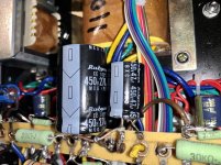
Is that a 150uF first filter cap that is loading the rectifier tube? OUCH! do not do that.
Instead, use a capacitor that is within the rectifier's rating, and then put more capacitance After the choke.
The schematic does not show any negative feedback. Good. The triode wired tubes should be good enough.
If you do have negative feedback, then a different output transformer might cause oscillations.
In that case, either the primary leads need to be swapped; or the negative feedback parts may need to be adjusted (two different output transformer models may not have the same inductance, not have the same phase response at high frequencies, and may not have the same high frequency roll off.
Was this a kit amplifier, or did it come already wired from the factory in China?
What kind of noise?
Do not give up hope, this could become an excellent sounding amplifier.
Why are you using the 6SN7 in Cascode mode?
Cascode tube stages are most often used in RF preamps, and in Radar IF amplifiers.
Are you hoping for linearity?
And, you are using a Cascode RF amplifier stage, without using grid stoppers in the two triodes of the cascode.
You want an Audio amplifier, not an RF amplifier stage.
As it is, there might be oscillations.
With the stacked triodes, the top triode cathode may have filament to cathode leakage, more possibility of noise or oscillation.
A single section of the 6SN7 is linear all by itself.
If you want linearity and gain = u (mu), then use an IXYS current source as the plate load of a single 6SN7 triode.
Or even simpler, just use a single 6SN7 triode, and a simple plate load resistor (you will get linearity, and perhaps gain = 80% of u (mu).
A Cascode amp has very high plate impedance at the output.
And you have a Cascode stage, it is not an SRPP stage (but I do not prefer SRPP stages either).
And, you do not have grid stopper resistors at the individual grids of the parallel output tubes.
As it is, it looks a lot like a Buttler Oscillator Circuit (the parasitics are "hidden", just stray C and stray wire inductances).
The parasitics might cause oscillations.
If one tube is hogging most of the current, the sound will be distorted.
To keep the two output tubes at nearly the same current, use individual self bias resistors (2 x 270 = 540 Ohms, so use two 500 Ohm resistors).
Put an individual bypass capacitor across each individual self bias 500 Ohm resistor.
Now you can measure the individual cathode voltages, and see if one tube is hogging the current.
The 1k resistor from the volume control pot is an incorrect attempt at providing a grid stopper.
But one end of all grid stoppers must be directly connected to the tab on the tube socket, and the other end goes to the other parts, like the volume control wiper, and the 470k grid leak resistor.
Is that a 150uF first filter cap that is loading the rectifier tube? OUCH! do not do that.
Instead, use a capacitor that is within the rectifier's rating, and then put more capacitance After the choke.
The schematic does not show any negative feedback. Good. The triode wired tubes should be good enough.
If you do have negative feedback, then a different output transformer might cause oscillations.
In that case, either the primary leads need to be swapped; or the negative feedback parts may need to be adjusted (two different output transformer models may not have the same inductance, not have the same phase response at high frequencies, and may not have the same high frequency roll off.
Was this a kit amplifier, or did it come already wired from the factory in China?
Last edited:
Amp
Hi yes I bought it like this from China.
Yes i had read about the first cap max capacitance. i replaced the first cap with 47uF and then added 270uf.
As for the tubes this is what came with it.
As for the noise after swapping transformers,
See this link
New transformer noise - YouTube
Making all the changes you speak of is too advancements for me but I can show a tech and ask them to do these mods for me.
Thx
Attachments

When all else fails, best bet is to put it back the way it was & start over. Then carefully observe what each change does. The truth will out!🙂
New transformers
Yes I did put back the originals. It works again... so it’s some kinda of issue with the new transformer inductance...
I guess with some one who has the knowledge of taking the new transformer inductance and calculate based on the circuit and adjust some of the components in the circuit to make the new transformers work.
Could it be just the coupling capacitor value needs to be changed?
Thx
The schematic does not show any negative feedback.
If they wired in negative feedback (and forgot to show it), and the new transformer phase connections was wrong, it could oscillate.
And even if it was wired correctly, the negative feedback could cause oscillation.
If the new transformer has much different frequency response at either the low frequency end, or at the high frequency end, that could be the problem.
Look to make sure that the actual wiring exactly matches the schematic.
Especially if they did connect negative feedback, be sure and let us know.
If there is no negative feedback, then a few things might be the cause of the problem
Stray capacitance and wiring placement
Ground loops
Insufficient separation of input stage B+ from output stage B+
and
Changing to an output transformer that presents a different reactive load to parallel output tubes that do not have grid stopper resistors.
Remember, even audio tubes can work at RF.
Parasitic inductance and parasitic capacitance are a part of real wiring.
An improperly configured parallel tube is a good candidate for a butler oscillator.
And oscillators can suffer from blocking or squeezing.
As to the input tube, it is a Cascode stage.
Those circuits may be on the verge of some kind of oscillation with the original transformers, and now with the new transformers are oscillating.
I do not like Cascode input stages. Cascode stages are made for RF amplification. And RF amplifiers can oscillate.
"I do not like Green Eggs and Ham, Green Eggs and Ham I do not like" - Dr. Seuss
Last edited:
Noise
Did u listen to the noise in my video? Might give an idea of what’s going on...
New transformer noise - YouTube
Thx
Did u listen to the noise in my video? Might give an idea of what’s going on...
New transformer noise - YouTube
Thx
Thanks.
I listened already.
Arcing.
Bad connection.
Squeezing (brief oscillations, followed by blocking).
Overrated parts.
Bad transformer insulation, on verge of arcing, followed by lower voltage, followed by arcing.
Who knows?
I listened already.
Arcing.
Bad connection.
Squeezing (brief oscillations, followed by blocking).
Overrated parts.
Bad transformer insulation, on verge of arcing, followed by lower voltage, followed by arcing.
Who knows?
Self bias resistors
Hi can u elaborate exactly how to install the self bias resistors..?
Can I show me on the schematic ?
Thx
Noise?
What kind of noise?
Do not give up hope, this could become an excellent sounding amplifier.
Why are you using the 6SN7 in Cascode mode?
Cascode tube stages are most often used in RF preamps, and in Radar IF amplifiers.
Are you hoping for linearity?
And, you are using a Cascode RF amplifier stage, without using grid stoppers in the two triodes of the cascode.
You want an Audio amplifier, not an RF amplifier stage.
As it is, there might be oscillations.
With the stacked triodes, the top triode cathode may have filament to cathode leakage, more possibility of noise or oscillation.
A single section of the 6SN7 is linear all by itself.
If you want linearity and gain = u (mu), then use an IXYS current source as the plate load of a single 6SN7 triode.
Or even simpler, just use a single 6SN7 triode, and a simple plate load resistor (you will get linearity, and perhaps gain = 80% of u (mu).
A Cascode amp has very high plate impedance at the output.
And you have a Cascode stage, it is not an SRPP stage (but I do not prefer SRPP stages either).
And, you do not have grid stopper resistors at the individual grids of the parallel output tubes.
As it is, it looks a lot like a Buttler Oscillator Circuit (the parasitics are "hidden", just stray C and stray wire inductances).
The parasitics might cause oscillations.
If one tube is hogging most of the current, the sound will be distorted.
To keep the two output tubes at nearly the same current, use individual self bias resistors (2 x 270 = 540 Ohms, so use two 500 Ohm resistors).
Put an individual bypass capacitor across each individual self bias 500 Ohm resistor.
Now you can measure the individual cathode voltages, and see if one tube is hogging the current.
The 1k resistor from the volume control pot is an incorrect attempt at providing a grid stopper.
But one end of all grid stoppers must be directly connected to the tab on the tube socket, and the other end goes to the other parts, like the volume control wiper, and the 470k grid leak resistor.
Is that a 150uF first filter cap that is loading the rectifier tube? OUCH! do not do that.
Instead, use a capacitor that is within the rectifier's rating, and then put more capacitance After the choke.
The schematic does not show any negative feedback. Good. The triode wired tubes should be good enough.
If you do have negative feedback, then a different output transformer might cause oscillations.
In that case, either the primary leads need to be swapped; or the negative feedback parts may need to be adjusted (two different output transformer models may not have the same inductance, not have the same phase response at high frequencies, and may not have the same high frequency roll off.
Was this a kit amplifier, or did it come already wired from the factory in China?
Hi can u elaborate exactly how to install the self bias resistors..?
Can I show me on the schematic ?
Thx
Attachments
maddmaxxdrummer,
The cathodes of the two output tubes are connected to each other, and from there they are connected to a single resistor in parallel with a 50V capacitor that both connect to ground.
I can not read the numbers on that schematic (270 Ohm 2W resistor and 220uF at 50V?) Correct?
That one resistor, and that one bypass cap are a Common self bias circuit (not individual self bias).
To change to individual self bias networks:
Break the connection of the output tubes two cathodes to each other.
Get four 270 Ohm 2 Watt resistors that have very closely matched resistance to each other.
Connect 2 in series (540 Ohm). Connect the other 2 in series (540 Ohm).
Connect one cathode to a self bias resistor: two 270 Ohm 2 Watt in series, to ground.
Connect a 220uF bypass capacitor across the 540 Ohm self bias resistance.
Connect the other cathode to a self bias resistor: two 270 Ohm 2 Watt in series, to ground.
Connect another 220uF 50V bypass capacitor across the 540 Ohm self bias resistance.
Now, each individual output tube cathode sees its own self bias network of 540 Ohm 2 Watt resistor and 220uF cap to ground.
Done.
The current in each output tube is the voltage across its 540 Ohm resistance divided by 540 Ohms.
V/540 = Amps. For example, If the voltage is 16V, the current is 0.0296A (29.6mA).
If the current in the two tubes is badly matched, it would be good to get a few tubes to find a pair that matches (one is either weak, or one is real strong)
Last edited:
Hi, thx for the explanation. I’m trying to picture this... is this explanation for one channel only? is it possible to have a diagram?
Last edited:
Diagram
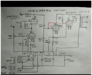
I’m assuming it’s like this
I used the original schematic and mark up on my iPhone... looks awful lol ...but maybe you’ll get it.. so the black marks are the 270ohm resistors in series.. with a 220uf across the whole 540ohm... the X in red is where i break the connection to the cathodes. I do the same to the other tube. Shown in my awful mark up Scribble lol
Is this correct?
Thx

You got it.
And so will others reading this thread.
2 individual self bias networks, instead of a shared bias network.
Double the resistance for each individual cathode.
Bypass capacitor for each cathode.
This is even more important for a push pull amplifier, it helps to balance the 2 plate currents. Push pull output transformers work better with balanced quiescent plate currents.
Diagram ?
Hi would u be able to make me a diagram?
Thx
With a 2.2k bottom triode self bias resistor, and dividing the B+ voltage between the bottom and the top triode sections, and with the 30k plate resistor, you are not going to over-dissipate a 12AU7 in the input stage.
You might try using another 2.2k self bias resistor in the top triode of the cascode.
That will make the voltages across the 2 triodes the same.
But be sure to use a bypass cap across the added self bias resistor to retain the cascode topology.
You may need to reduce both of the 2.2k self bias resistors, the original one, and the added one.
The B+ is divided between the bottom triode, the top triode, and the 30k plate resistor.
I suggest using the JJ 12AU7 from Eurotubes.com.
The filament is spiral wound, not the common filament of today.
The original Amperex spec for the 12AU7 was spiral wound, not just serial up and down multiple filament wires.
The spiral filament may give less hum and noise.
Eurotubes.com retests the JJ tubes for hum and noise.
Telefunken should work good too (but do take a look to see if the filament wires are spiral wound).
Hi would u be able to make me a diagram?
Thx
- Home
- Amplifiers
- Tubes / Valves
- Has anyone tried a "12AU7 to 6SN7 Adapter"?