Something like this?
dado
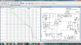
No, sorry it was not clear. What I meant was that the 0 dB line should be -180 phase (= 0 PM). Not 200 phase as in this plot. In the previous post it varies between plots. In the middle it's -200 but the others are -240. Inconsistency makes comparisons harder.
A consistent use of 0 dB = 0 PM would make it instantly obvious if an amp was stable
Best wishes
David.
In these discussions of comparative stability it is easier if plots have the 0 dB line as also the 0 phase margin.
Is there a convenient way to force this in LTSpice?
David
When the plot windows is focused, press CTRL+A and type "1" into Expression field, without quotation marks.
nicer pictures
To all LT spice user:
In order to enhance the readability, also change the background color of the graphs from black to white and regarding schematics from grey also to white and without grid.
Thank you.
Cheers,
E.
To all LT spice user:
In order to enhance the readability, also change the background color of the graphs from black to white and regarding schematics from grey also to white and without grid.
Thank you.
Cheers,
E.
To all LT spice user:
In order to enhance the readability, also change the background color of the graphs from black to white and regarding schematics from grey also to white and without grid.
Thank you.
Cheers,
E.
I do not think this is more readable, only better for the printer toners.
dado
Attachments
To me the schematic looks much better, the graph however, is too much cluttered with grid lines. Is it possible to reduce the number of vertical grid lines?
Cheers,
E.
edit: I don't like books either printed on grey or black paper. 😉
Cheers,
E.
edit: I don't like books either printed on grey or black paper. 😉
Last edited:

When the plot windows is focused, press CTRL+A and type "1" into Expression field, without quotation marks.
That doesn't alter the phase axis scale.
It just plots a constant value of 1 with the associated phase of 0.
Best wishes
David
No, I was right the first time. -1 will give lines at 0 dB and -180 deg. Not as good as aligned axes, but I find this helps.
Last edited:
Bad caps
Hi Bob,
Out of curiosity, I did some measurements on a few BAD electrolytics, i.e. a polar caps of 1000uF, 10V (and 10 years old). Also using two of them, either back-to-back or anti parallel, doesn't help much. Distortion is way too high for a 1ppm amp. See figure below for results.
Contrary to what might be expected, even harmonics did not decrease by using two caps. Perhaps because they were not exactly matched.
Cheers,
E.
I said a GOOD electrolytic 🙂.
Cheers,
Bob
Hi Bob,
Out of curiosity, I did some measurements on a few BAD electrolytics, i.e. a polar caps of 1000uF, 10V (and 10 years old). Also using two of them, either back-to-back or anti parallel, doesn't help much. Distortion is way too high for a 1ppm amp. See figure below for results.
Contrary to what might be expected, even harmonics did not decrease by using two caps. Perhaps because they were not exactly matched.
Cheers,
E.
Attachments

Edmond, you need to share your practical results over in the Blowtorch thread. There's discussion on cap distortion underway.
My CD to amp output signal chain has 1 cap - a Nichicon 16V electrolytic 1000uF.
My CD to amp output signal chain has 1 cap - a Nichicon 16V electrolytic 1000uF.
bad caps
Hi Andrew,
That's not my favorite thread.
Whether it distorts (and to what extent) depends on the voltage across cq. current through that cap, which in turn depends on the frequency. In my test setup the voltage was 30...60mV, being enough to raise the distortion above 1ppm. So, can you measure (or calculate) the voltage across your cap at say 20Hz?
Cheers,
E.
Edmond, you need to share your practical results over in the Blowtorch thread. There's discussion on cap distortion underway.
Hi Andrew,
That's not my favorite thread.
My CD to amp output signal chain has 1 cap - a Nichicon 16V electrolytic 1000uF.
Whether it distorts (and to what extent) depends on the voltage across cq. current through that cap, which in turn depends on the frequency. In my test setup the voltage was 30...60mV, being enough to raise the distortion above 1ppm. So, can you measure (or calculate) the voltage across your cap at say 20Hz?
Cheers,
E.
-3dB at 2Hz
Peak current through the cap at 65V is 13mA, so the voltage across the cap at 20Hz is still mV
After reading about the PGP, I decided caps were not as big s problem as some make out. ;-)
Practically speaking, the e-Amp sounds wonderful, so I don't feel the urge to use a servo, though of course I think they are more sexy than a cap.
servo dilemma
Are we talking about a cap in the same position, i.e. in the global NFB path?
The PGP amp has a bi-polar cap. According to Cyril Bateman's measurements it makes a lot of difference: ~20dB, i.e. well above or well below the 1ppm barrier. But if other distortions of your e-Amp are significant higher, I also wouldn't feel the urge to use a servo.
As for servo's, I don't think there's anything sexy about it. Instead, it's a rather clumsy kludge, comprising some 24 additional components (incl. the PSU) and eating up valuable board space. Nevertheless, I'm afraid I have no choice, simply because there ain't no decent caps in the range of 100...1000uF.
As for bi-polar caps, I don't trust them because of aging (drying electrolyte and forming of aluminum hydroxide).
Cheers,
E.
Last edited:
Why not use MKP or MKT caps , since there s high values
such as 1000uF as well , although the higher values from Wima
are mainly 220uF , what i m using for GNFB DC blocking.
Values as high as 4500uF seems available in the automotive
portfolio products.
An insightfull link about caps , anyway !
WIMA
WIMA
such as 1000uF as well , although the higher values from Wima
are mainly 220uF , what i m using for GNFB DC blocking.
Values as high as 4500uF seems available in the automotive
portfolio products.
An insightfull link about caps , anyway !
WIMA
WIMA
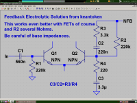
Edmond, consider this.
With FETs, smaller low-tolerance caps could be used. The base impedance of the transistors should be fairly high, which may eliminate using this scheme with low-feedback designs. For balance, Hfe matching becomes important.
Noise can be lower due to smaller feedback resistors, and BW is increased because at HF the feedback network output impedance is low.
Attachments
Where to buy (in Europe) and how large are these monsters?
Cheers,
E.
Hi , Edmond
The automotive models seems exclusively high voltage , 600V at least,
with huge 80x120mm dimensions , although who would need such
extreme values as 600V/1.6mR ESR/30A at 1KHZ/ for a poor
dividor that will handle at most a few mV and uA....😉
The 220uF/50V MKP is 37.5mm , quite usable , particularly with
medium Z feedback network, and should be available in Europe
without difficulty.
Indeed , increasing the NFB network impedance to 33K/1K
or even 68K/2K allow manageable MKP capS sizes and values
to be used.
Of course , the input stage has to be designed accordingly ,
with low enough tail current as well as very high gain transistors.
- Status
- Not open for further replies.
- Home
- Amplifiers
- Solid State
- Has anyone seen this front-end before?