Are we talking about a cap in the same position, i.e. in the global NFB path?
Yes
The PGP amp has a bi-polar cap. According to Cyril Bateman's measurements it makes a lot of difference: ~20dB, i.e. well above or well below the 1ppm barrier. But if other distortions of your e-Amp are significant higher, I also wouldn't feel the urge to use a servo.
20dB difference, but distortion is already rock bottom, so I feel no urge to use anything else. BTW, are you talking about low frequency distortion or something else? AP distortion plots on oversized electrolytics (and not bipolar) show zero distortion.
As for servo's, I don't think there's anything sexy about it. Instead, it's a rather clumsy kludge, comprising some 24 additional components (incl. the PSU) and eating up valuable board space. Nevertheless, I'm afraid I have no choice, simply because there ain't no decent caps in the range of 100...1000uF.
Yes, unless you have +-10-15V realidy available, then it does require a lot of additional components. If you use zener references for the cascodes then this is a convenient place to tap off the servo supply. As for bi-polar caps, I don't trust them because of aging (drying electrolyte and forming of aluminum hydroxide).
Yes, aging is always an issue.
Wahab, those 220uF are ployester - they are known to have distortion problems - see Douglas Self 'Small Signal Design' for a plot.
Electrolytics are a good choice in this application in my view, unless you are prepared go to the trouble of a servo.
Electrolytics are a good choice in this application in my view, unless you are prepared go to the trouble of a servo.
Tian or Middlebrook Probe?
I have started to study the details of loop probes because it looks to me that loops in TMC are not well modelled by idealized loops so a simple probe may be inaccurate.
It is claimed that the Middlebrook GFT probe is the only theoretically correct technique. Possibly the difference with Tian is not of practical consequence.
Edmond, did you use the Tian probes for the loop plots on the website?
Have you (or others in this thread) looked at this issue?
Best wishes
David
Thanks Damir.
I will have a look at it later on, because at the moment I'm finishing the adaption* of the schematic to the PCB version (a lot of work). Besides, LS protection will be put on a separate PCB and will be one of the next steps.
* That also means the incorporation of a DC servo, making the amp even more complex. As a matter of fact, I'm doing it with huge aversion: adding (read: wasting) needlessly a dozen extra components, simply because some gurus say that any electrolytic cap (no matter what type or brand) in the NFB loop is bad.
Cheers,
E.

I've been dealing with the same issue in MF80, my 80W symmetrical MOSFET amp. What I have learnt is that decent electrolytes themselves don't cause (for me) measurable THD differences at the higher frequencies. However, if the cap is too low, the DC average starts drifting in proportion to the output signal and as such starts to cause THD with the much lower frequencies (Envelope Decay Distortion). On the THD plot this is clearly visible by a plot that starts out with high THD and lowers exponentially the higher the frequency is, down to the overall THD of the amp itself.
I just threw in a cap that with the NFB creates a -3dB point at around 2H and consequently, an input lowpass filter of 1Hz rollon. Since then, the NFB cap has zero measurable effect on THD (Measured with a 192KHz/24bit soundcard).
Since my new amp design uses J-FETs for the input together with an inverting topology, i.e. virtual ground at one of the J-FET inputs I no longer need an NFB cap and will just put an offset pot in the input LTP, or use the offset control of an opamp as the very first input stage to drive the low impedance of the J-FET input.
I have only used the Tian et al probe technique.
Harry Dymond mentions in his paper (in the addendum IIRC) that some of the techniques do not model loop gain acurately once it falls below 0dB.
Harry Dymond mentions in his paper (in the addendum IIRC) that some of the techniques do not model loop gain acurately once it falls below 0dB.
". . .some gurus . . ."
I am sure Bob won't hold it against you if you use a cap. JC on the other hand . . . .
I am sure Bob won't hold it against you if you use a cap. JC on the other hand . . . .
Wahab, those 220uF are ployester - they are known to have distortion problems - see Douglas Self 'Small Signal Design' for a plot.
Electrolytics are a good choice in this application in my view, unless you are prepared go to the trouble of a servo.
Quite possible , although i wonder at which currents and voltages
theses caps show tangible distorsion numbers.
Anyway , i use electrolytics as well , their much decried
behavior has surely more to do with marketing considerations
than with real technical basis that are raised by curious people
who can hand match whole series of semiconductors from a single
manufacturer , yet , it seems that selecting a cap from a serious
manufacturer , and there are plenty of them , is not professional...🙄
a square-like square wave
Hi Keane,
I was thinking along the same lines. Again same minds. 😀
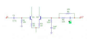
But I opt for lower impedances and different R/C ratios (fig.1).
The reason for that is twofold:
1. Lower noise.
2. Nicer square wave response at 20Hz.
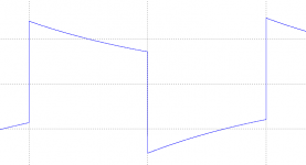
With a single FB resistor of 6k we get a heavily tilted square wave (fig.2)
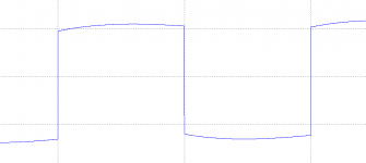
With two 12k resistors and 1uF in the FB path the square wave becomes more square-like (fig.3). But to get this picture, C2 needs to be quite large: 500...1000uF.
Since the DC resistance seen by both inputs is the same (and assuming matched trannies), the offset voltage is quite low.
Cheers,
E.
Edmond, consider this.
With FETs, smaller low-tolerance caps could be used. The base impedance of the transistors should be fairly high, which may eliminate using this scheme with low-feedback designs. For balance, Hfe matching becomes important.
Noise can be lower due to smaller feedback resistors, and BW is increased because at HF the feedback network output impedance is low.
Hi Keane,
I was thinking along the same lines. Again same minds. 😀
But I opt for lower impedances and different R/C ratios (fig.1).
The reason for that is twofold:
1. Lower noise.
2. Nicer square wave response at 20Hz.
With a single FB resistor of 6k we get a heavily tilted square wave (fig.2)
With two 12k resistors and 1uF in the FB path the square wave becomes more square-like (fig.3). But to get this picture, C2 needs to be quite large: 500...1000uF.
Since the DC resistance seen by both inputs is the same (and assuming matched trannies), the offset voltage is quite low.
Cheers,
E.
Attachments
evil caps
Hi Andrew,
The point is that I'm aiming for even lower distortion (<1ppm), also at very low frequencies (20Hz).
The measurement floor of an AP is about -115dB. No wonder that you get 'zero distortion'. However, the measurement floor of my setup is about -140dB, much more sensitive. Only then the distortion of the electrolytics will show up clearly.
Well, I'm using zeners in the tail current sources and I'm using these as references for the +/-15V supplies as well. Nevertheless, I still need 14 additional components to complete the PSU.
What about solid polymer aluminum caps? Any info about distortion figures?
Cheers,
E.
20dB difference, but distortion is already rock bottom, so I feel no urge to use anything else. BTW, are you talking about low frequency distortion or something else? AP distortion plots on oversized electrolytics (and not bipolar) show zero distortion.
Hi Andrew,
The point is that I'm aiming for even lower distortion (<1ppm), also at very low frequencies (20Hz).
The measurement floor of an AP is about -115dB. No wonder that you get 'zero distortion'. However, the measurement floor of my setup is about -140dB, much more sensitive. Only then the distortion of the electrolytics will show up clearly.
Yes, unless you have +-10-15V realidy available, then it does require a lot of additional components. If you use zener references for the cascodes then this is a convenient place to tap off the servo supply.
Well, I'm using zeners in the tail current sources and I'm using these as references for the +/-15V supplies as well. Nevertheless, I still need 14 additional components to complete the PSU.
Yes, aging is always an issue.
What about solid polymer aluminum caps? Any info about distortion figures?
Cheers,
E.
[..]
Edmond, did you use the Tian probes for the loop plots on the website?
[..]
Best wishes
David
Yes, I do.
Cheers,
E.
Hi MagicBox,
Thanks for your response, but I stick with BJTs at the input and using a non-inverting topology. So I can't use your solution for solving the offset issue.
Cheers,
E.
Thanks for your response, but I stick with BJTs at the input and using a non-inverting topology. So I can't use your solution for solving the offset issue.
Cheers,
E.
And now I'm going back to debugging my S/W distortion analyzer. The last time I looked at it was in 2005. So it needs a bit of effort to understand the code, despite I've written it by myself.
Cheers,
E.
Cheers,
E.
Hi Edmond,
Oh I wasn't really trying to offer a solution, just chiming in with my experiences. From the sound of it though, you really want to go for an accurate DC offset though without the associated distortion. Regarding it a no-compromize design, I would definitely add the DC servo and be done with it. If you eliminate the use of an opamp and use a discrete LTP with integrator you can possibly omit any additional powersupplies for the sake of powering opamps and continue to use the inputstage powersupply itself.
Oh I wasn't really trying to offer a solution, just chiming in with my experiences. From the sound of it though, you really want to go for an accurate DC offset though without the associated distortion. Regarding it a no-compromize design, I would definitely add the DC servo and be done with it. If you eliminate the use of an opamp and use a discrete LTP with integrator you can possibly omit any additional powersupplies for the sake of powering opamps and continue to use the inputstage powersupply itself.
DC Trimm
Hello Edmond.
If the amp your building will work with a trimmer pot (to null trim the DC output) you should accommodate it in the design provided it does not drift too much with temperature. By all means include a cap , but it looks like you dont need one with this amp.
I personally think you can live with a one off amp configured like this.
Regards
Arthur
Last edited:
Hi Arthur,
Regrettably it doesn't work without that evil cap. Because, without it, the inputs don't see equal DC impedances.
Cheers,
E.
Regrettably it doesn't work without that evil cap. Because, without it, the inputs don't see equal DC impedances.
Cheers,
E.
software issues
/OT
After all that time, seven years, I was afraid I had unlearned C++ and understanding (my own) code of the distortion analyzer. Happily, that wasn't the case and I found the bug. It appeared to be a false error msg and it was easy to repair. So don't worry about my measurements; the figures I've posted here are correct.
Another issue was finding the right driver for the sound card, a 'Waveterminal 192X'. For playback of music I'm using MME drivers, but for the distortion analyzer I prefer ASIO drivers. The problem is that not all driver versions from ESI work correctly, that is, sometimes the MME driver is okay and the ASIO doesn't work, or the other way around. Finally I found one, version 4.41, where both MME and ASIO as well do function properly. 🙂
Cheers,
E.
And now I'm going back to debugging my S/W distortion analyzer. The last time I looked at it was in 2005. So it needs a bit of effort to understand the code, despite I've written it by myself.
/OT
After all that time, seven years, I was afraid I had unlearned C++ and understanding (my own) code of the distortion analyzer. Happily, that wasn't the case and I found the bug. It appeared to be a false error msg and it was easy to repair. So don't worry about my measurements; the figures I've posted here are correct.
Another issue was finding the right driver for the sound card, a 'Waveterminal 192X'. For playback of music I'm using MME drivers, but for the distortion analyzer I prefer ASIO drivers. The problem is that not all driver versions from ESI work correctly, that is, sometimes the MME driver is okay and the ASIO doesn't work, or the other way around. Finally I found one, version 4.41, where both MME and ASIO as well do function properly. 🙂
Cheers,
E.
Will you share your distotion analyzer with us? There is need of something that can be built by DIYers that can emulate to some extent the AP - The oscillator source is always the issue and of course getting down to circa -120dB measurement capability (ok, I know that's not good enought for you ;-)
Will you share your distotion analyzer with us? There is need of something that can be built by DIYers that can emulate to some extent the AP - The oscillator source is always the issue and of course getting down to circa -120dB measurement capability (ok, I know that's not good enought for you ;-)
That would be interesting, as the Waveterminal 192X D/A has only 106dB of dynamic range. Compare to the PCM1792 D/A chip (to be found in high performance sound cards like the Asus Essence STX) with 127-132dB dynamic range.
The Waveterminal 192X D/A is not exactly appropiate to source signal for a <1ppm amplifier. To add insult to injury, being an internal sound card, any attempt to measure single ended amplifiers will hit the spurious noise barrier, most likely around -100dB.
Agree that the W192X is somewhat short but the Asus will do no better than 118dB
in real world, as in the recent Xonar PCIE , despite a PCM1796 and even when
swapping the op amps for LM49720s.
in real world, as in the recent Xonar PCIE , despite a PCM1796 and even when
swapping the op amps for LM49720s.
Will you share your distotion analyzer with us? There is need of something that can be built by DIYers that can emulate to some extent the AP - The oscillator source is always the issue and of course getting down to circa -120dB measurement capability (ok, I know that's not good enought for you ;-)
Hi Andrew,
Not now, as the software and documentation isn't finished yet. Also I'm not sure it's bug free. On top of that, there will be many question and requests for adaption to other sound cards. That means that there will be no time left over for building my amp.
In the event that all these projects have been been finished, I will ask a small amount of money for it, because I've invest so much time (3 years) in writing the software.
Cheers,
E.
- Status
- Not open for further replies.
- Home
- Amplifiers
- Solid State
- Has anyone seen this front-end before?