Regarding the ITU-R IMD test (19 and 20kHz), how is the level of IMD products exactly defined? Is it WRT the amplitude of one of the test tone, or is it WRT to the RMS value of both amplitudes, being sqrt(2) higher?
Cheers,
E.
Cheers,
E.
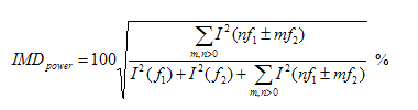
Intermodulation distortion is (should be) calculated as the square root of the ratio of power sum of intermodulation products components to the total signal power.
Then it is WRT to one of the amplitudes of the test signals (assuming that both amplitudes are equal). Thanks BV.
Cheers,
E.
Cheers,
E.
It should be "ratio of power sum of intermodulation products components to the total signal power" , so power of both test signals (for closely spaced test signals, with f2 / f1 < 2 , as is 19/20kHz CCIF).
Okay. So if f1 and f2 are close together and both have amplitude A, what is according to you total signal power expressed in terms of A?
edit: So, what's the answer?
edit: So, what's the answer?
Last edited:
>Maybee language barrier
Clearly a language barrier.
So, I'll put my question another way:
Suppose we have a 1Veff 19kHz sine and a 1Veff 20kHz sine.
What's the RMS value of the sum of these signal? (expressed in volts)?
I'm not asking for a formula, just asking for a number.
Clearly a language barrier.
So, I'll put my question another way:
Suppose we have a 1Veff 19kHz sine and a 1Veff 20kHz sine.
What's the RMS value of the sum of these signal? (expressed in volts)?
I'm not asking for a formula, just asking for a number.
Yes, top of the range AP comes in at 50k IIRC. I signed off the budget for one for the Tokyo lab 2 or 3 years ago. The old one was written off but someone got to it before me. Bastard.
The current range from AP has an option for 24 bit @ 1MHz FFT...
jan
IMD
In post #726 I made a stupid error: I confused peak amplitude with effective amplitude (in my S/W distortion analyzer peak values are used for defining amplitudes, hence the error). Sorry for the confusing. (clearly I'm getting old)
Anyhow, the (obvious!!!) answer is simply: eff. (rms) amplitude of the summed signal equals the root of summed squares of the individual eff. amplitudes.
Actually, this was what I always thought, but my software, messing with effective and peak values, made me to hesitate.
Cheers,
E.
Maybee language barrier.. Answer is in posted formula. f1, f2 are test signals, nf1, mf2 IMD products.
In post #726 I made a stupid error: I confused peak amplitude with effective amplitude (in my S/W distortion analyzer peak values are used for defining amplitudes, hence the error). Sorry for the confusing. (clearly I'm getting old)
Anyhow, the (obvious!!!) answer is simply: eff. (rms) amplitude of the summed signal equals the root of summed squares of the individual eff. amplitudes.
Actually, this was what I always thought, but my software, messing with effective and peak values, made me to hesitate.
Cheers,
E.
Suppose we have a 1Veff 19kHz sine and a 1Veff 20kHz sine.
What's the RMS value of the sum of these signal? (expressed in volts)?
.
Hi , Edmond
It is 2V RMS.
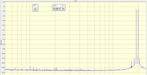
You certainly need a new sound card. Here's an oldie (5 years) MAudio-192 PCI that I got from a flea market, with 19+20KHz generated on the same left ch DAC (obviously not ideal). Overall IMD (not sure how much is DAC generation and how much is ADC conversion) is 17ppm and the 1KHz is at -128dB. 192KHz, 1Msamples, 100 averages, 0dB = 3.774Vrms, flat top window for maximum amplitude accuracy. One important note: this sound card has balanced analog I/O. A single ended card like the Asus (I also have one) has much more garbage on the FFT.
Not sure what you mean by "with/without attenuation of the test sines" there's not much of an effect in modifying the components amplitude between 200mV-2V in my setup.
Anyway, I would be curious how you are summing two 1V components and how you are estimating the distortion of such a summing setup. Even with resistive summing, you can't ignore the loading effect on the DAC output stage (which is an opamp). If the resistors are large, then the noise floor is affected and the output impendance will be high. Buffering is just another distortion source, etc...
Attachments
IMD
Hi Wahab,
Sorry, i disagree.
I'm pretty sure that what I said in post #730 is valid. I've checked it by means of a dumb brute force method in software:
I summed zillions of samples of the square of f1, f2 and the sum of (f1+f2), respectively. The peak amplitude of f1 and f2 was 1.0.
Then I divided the sums by the # of samples and took the square root of it. In doing so, I got the rms value of f1, f2 and (f1+f2).
The rms value was 0.707 for the individual signals and the rms value of the two signals summed together was 1.0. IOW, this is equal to the RMS of the two effective amplitudes of f1 and f2, thus not simply the sum of two of them.
I also checked it with a (peak) amplitude of f1 = 1 and amplitude of f2 = 2. RMS rules!
BUT... if you were talking about peak amplitudes, then the peak amplitude of the sum signal is simply the sum of the individual peak amplitudes (which, btw, makes no -or less- sense in defining the IMD as percentage)
edit1: So I stick to the formulas given by BV.
edit2: Perhaps this discussion looks trivial, but I search the web several times and I never could find an exact definition of percentage IMD, hence my dumb questions.
Cheers,
E.
Hi , Edmond
It is 2V RMS.
Hi Wahab,
Sorry, i disagree.
I'm pretty sure that what I said in post #730 is valid. I've checked it by means of a dumb brute force method in software:
I summed zillions of samples of the square of f1, f2 and the sum of (f1+f2), respectively. The peak amplitude of f1 and f2 was 1.0.
Then I divided the sums by the # of samples and took the square root of it. In doing so, I got the rms value of f1, f2 and (f1+f2).
The rms value was 0.707 for the individual signals and the rms value of the two signals summed together was 1.0. IOW, this is equal to the RMS of the two effective amplitudes of f1 and f2, thus not simply the sum of two of them.
I also checked it with a (peak) amplitude of f1 = 1 and amplitude of f2 = 2. RMS rules!
BUT... if you were talking about peak amplitudes, then the peak amplitude of the sum signal is simply the sum of the individual peak amplitudes (which, btw, makes no -or less- sense in defining the IMD as percentage)
edit1: So I stick to the formulas given by BV.
edit2: Perhaps this discussion looks trivial, but I search the web several times and I never could find an exact definition of percentage IMD, hence my dumb questions.
Cheers,
E.
Last edited:
Hi , Edmond
Well , out of curiosity , i did simply put two generators in serial and checked
the resulting output signal , wich at first look , and only looking at the envelloppe , is vaguely a sinusoidal function whose amplitude is the sum of the two signals amplitudes , hence my conclusion that it is 2V for two 1V signals.
Of course , with parralleled generators and assuming that thay have same
output Z , summing two 1V signal would yield a 1V total signal.
For obvious reasons , only this latter case is to be considered
with a sound card.
Attachments
Hi Wahab,
Of course, the envelope (=peak value) is simply the sum of the two signals amplitudes, that's what I also said in my previous post. I've never denied that.
But that is not the value we need for calculation of the relative IMD, that is, as a percentage of the input signal. According to BV, and I believe he is right, we should use the "energy" (=rms value) of the signals. For the summed input signal, this value is half of the peak value (no, it has nothing to do with the resistors; that's another story).
As for the individual IMD products, the rms value is 0.707 (=sqrt 0.5) of the peak value, of course.
The point is that if we use peak values instead of rms values for calculation of the relative IMD, we get a lower value: (1/0.707)/2= 0.707 lower. Therefore I asked how to do the calculation. That was all about it.
Cheers,
E.
The current range from AP has an option for 24 bit @ 1MHz FFT...
jan
Hello Jan
Do you know what A/D converter they use to get 24bit at 1Mhz in the AP
Regards
Arthur
Hi Wahab,
Of course, the envelope (=peak value) is simply the sum of the two signals amplitudes, that's what I also said in my previous post. I've never denied that.
But that is not the value we need for calculation of the relative IMD, that is, as a percentage of the input signal. According to BV, and I believe he is right, we should use the "energy" (=rms value) of the signals. For the summed input signal, this value is half of the peak value (no, it has nothing to do with the resistors; that's another story).
As for the individual IMD products, the rms value is 0.707 (=sqrt 0.5) of the peak value, of course.
The point is that if we use peak values instead of rms values for calculation of the relative IMD, we get a lower value: (1/0.707)/2= 0.707 lower. Therefore I asked how to do the calculation. That was all about it.
Cheers,
E.
Hi, Edmond
Effectively , the RMS value of the reference signal is to be compared
to the RMS value of the IMD products for the calculus to be correct.
You certainly need a new sound card.
Very true, but which one?
Here's an oldie (5 years) MAudio-192 PCI that I got from a flea market, with 19+20KHz generated on the same left ch DAC (obviously not ideal). Overall IMD (not sure how much is DAC generation and how much is ADC conversion) is 17ppm and the 1KHz is at -128dB. 192KHz, 1Msamples, 100 averages, 0dB = 3.774Vrms, flat top window for maximum amplitude accuracy.
Indeed, your sound card does it a lot better, at least at 1kHz. However, the overall IMD is rather high. So I wonder how it was computed, i.e. which IMD product were summed together. One thing makes me suspicious: the height of the IMD components near the test frequencies. It looks as if there is a lot of "leakage" in your FFT.
(btw, my spectra don't show any leakage)
One important note: this sound card has balanced analog I/O. A single ended card like the Asus (I also have one) has much more garbage on the FFT.
Mine has also single ended outputs, but the software takes care of removing every garbage that's unrelated to the frequencies of interest (by means of synchronous detection, averaging, etc.)
For THD measurements I put a critically coupled LC bandpass filter behind the DAC. So the output has been isolated (from ground) anyhow.
Not sure what you mean by "with/without attenuation of the test sines" there's not much of an effect in modifying the components amplitude between 200mV-2V in my setup.
I mean that only the 19/20kHz are selectively attenuated. Thus not the 1kHz IMD component. This way the IMD from the ADC is greatly reduced. See also post #714 from jcx.
Anyway, I would be curious how you are summing two 1V components and how you are estimating the distortion of such a summing setup. Even with resistive summing, you can't ignore the loading effect on the DAC output stage (which is an opamp). If the resistors are large, then the noise floor is affected and the output impendance will be high. Buffering is just another distortion source, etc...
I did it the simple way: just using two resistors of 12k. In this case I'm aware of a possible interaction between the op-amp outputs of the DAC channels (loading effect). But, as it appeared, the main cause of the poor DAC performance lies somewhere else. This has been proved by the fact that if I'm using two different sounds cards for generating the test sines, the DAC IMD is much lower. Why this is I don't know yet. Perhaps the multi channel DAC chip (AK4355) suffers from inter channel modulation. Anyhow, it is not caused by the simple resistive summer.
BTW, syn08 has also tried an op-amp (AD797?) based summing circuit. Then the two resistors are tied to a virtual ground. Yet he got better results (a lower measurement floor) by doing it the "simple way".
Hello Jan
Do you know what A/D converter they use to get 24bit at 1Mhz in the AP
Regards
Arthur
Hi Arthur,
Perhaps AP uses this ADC from NI: National Instruments Flex II ADC Technology - The Flexible Resolution Technology inside the NI PXI-5922 Digitizer - Developer Zone - National Instruments
Cheers,
E.
- Status
- Not open for further replies.
- Home
- Amplifiers
- Solid State
- Has anyone seen this front-end before?