24Bit A/D 1MHz
Hello Edmond
Thanks for the link NI link very interesting. They are using a continuous time Delta sigma converter a discrete implementation as apposed to an off the shelf chip
I was guessing that AP might have used the AD7760 or some other chip.
Regards
Arthur
Hello Edmond
Thanks for the link NI link very interesting. They are using a continuous time Delta sigma converter a discrete implementation as apposed to an off the shelf chip
I was guessing that AP might have used the AD7760 or some other chip.
Regards
Arthur
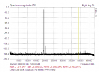
Something like LYNX L22, if you mean it serious. BTW, 19,20kHz amplitude is -6,02dBV (RMS), overal RMS (including distortions) is -2,6dBV(RMS). Both tones are generated in one DAC.Very true, but which one?
Attachments
Last edited:
@ Arthur: I almost forgot that chip. Indeed, an AD7760 is more likely to be used by AP.
@ BV: Sure, a Lynx L22* is a nice card, though a bit expensive. Also, isn't a L22 a bit outdated, as the current generation of high-end op-amps, DACs and ADCs are better? (the AD7760, for example)
* Once I could get one on eBay, but someone else has overbid me.
Cheers,
E.
@ BV: Sure, a Lynx L22* is a nice card, though a bit expensive. Also, isn't a L22 a bit outdated, as the current generation of high-end op-amps, DACs and ADCs are better? (the AD7760, for example)
* Once I could get one on eBay, but someone else has overbid me.
Cheers,
E.
Hard to find better card..If you know some better , why not.Also, isn't a L22 a bit outdated, as the current generation of high-end op-amps, DACs and ADCs are better?
Very true, but which one?
Indeed, your sound card does it a lot better, at least at 1kHz. However, the overall IMD is rather high. So I wonder how it was computed, i.e. which IMD product were summed together. One thing makes me suspicious: the height of the IMD components near the test frequencies. It looks as if there is a lot of "leakage" in your FFT.
(btw, my spectra don't show any leakage)
Mine has also single ended outputs, but the software takes care of removing every garbage that's unrelated to the frequencies of interest (by means of synchronous detection, averaging, etc.)
For THD measurements I put a critically coupled LC bandpass filter behind the DAC. So the output has been isolated (from ground) anyhow.
I mean that only the 19/20kHz are selectively attenuated. Thus not the 1kHz IMD component. This way the IMD from the ADC is greatly reduced. See also post #714 from jcx.
I did it the simple way: just using two resistors of 12k. In this case I'm aware of a possible interaction between the op-amp outputs of the DAC channels (loading effect). But, as it appeared, the main cause of the poor DAC performance lies somewhere else. This has been proved by the fact that if I'm using two different sounds cards for generating the test sines, the DAC IMD is much lower. Why this is I don't know yet. Perhaps the multi channel DAC chip (AK4355) suffers from inter channel modulation. Anyhow, it is not caused by the simple resistive summer.
BTW, syn08 has also tried an op-amp (AD797?) based summing circuit. Then the two resistors are tied to a virtual ground. Yet he got better results (a lower measurement floor) by doing it the "simple way".
The "leakage in the FFT is due to the window type (flat top). A Blackman window looks much better, but then the component values are less accurate. The IMD using Blackman window is 11ppm.
If you look at those components around 19-20KHz, they account for about 7ppm, 7ppm, 4ppm (ref: 0dB), hence the total is 11ppm. The balance to 17ppm is probably the components around other frequencies. I have no idea how spectraplus computes the IMD, but it's consistent with Rightmark, so I would assume it is correct.
Again, the 19k and 20k components are generated in the same DAC, so I would expect generating them in separate DAC's (even on the same chip) would lead to much better IMD results. I would suspect the 17ppm IMD result is actually the IMD of the DAC output stage opamp (1/2 NE5532).
Get and Asus Xonar PCIe, you can't go wrong with that. I have no idea what you are doing in your hardware and software, but you definitely need to cross check your results against other methods, to make sure you are not introducing artifacts (or removing significant information).
PS: I paid 10 squid for the MAudio 192.
Last edited:
The "leakage in the FFT is due to the window type (flat top). A Blackman window looks much better, but then the component values are less accurate. The IMD using Blackman window is 11ppm.
Windowing, that's precisely the problem.
I don't need windows (except from MS) 😀
If you look at those components around 19-20KHz, they account for about 7ppm, 7ppm, 4ppm (ref: 0dB), hence the total is 11ppm. The balance to 17ppm is probably the components around other frequencies. I have no idea how spectraplus computes the IMD, but it's consistent with Rightmark, so I would assume it is correct.
Rightmark sucks, see: NwAvGuy: RightMark Audio Analyzer
You better write and use your own software, as only then you know exactly what is happening inside.
Again, the 19k and 20k components are generated in the same DAC, so I would expect generating them in separate DAC's (even on the same chip) would lead to much better IMD results. I would suspect the 17ppm IMD result is actually the IMD of the DAC output stage opamp (1/2 NE5532).
I don't think so. I guess the 17ppm stems from the FFT leakage.
Get and Asus Xonar PCIe, you can't go wrong with that. I have no idea what you are doing in your hardware and software, but you definitely need to cross check your results against other methods, to make sure you are not introducing artifacts (or removing significant information).
PS: I paid 10 squid for the MAudio 192.
I always check my results with other methods. No need to emphasize on that.
Hello Edmond
I am curious about your software development , you are using C++ may I ask what IDE you are using. Can you suggest a link on how to access the raw measurement data of computer sound card.
Regards
Arthur
I am curious about your software development , you are using C++ may I ask what IDE you are using. Can you suggest a link on how to access the raw measurement data of computer sound card.
Regards
Arthur
Hi Arthur,
>IDE
I'm using my good old Symantec C++ compiler V7.50. The package is 15 year old, but still nothing can compete with it when comes to speed and compactness. *
>raw data
That's not available. The only thing I can save and provide is a FFT of the residual (in a proprietary data format). Sorry.
Cheers,
E.
*/OT
It also compiles ridiculous fast. Compiling the whole analyzer takes about 0.5 sec.
But what amazed me even more is that it still works properly after I simply copied the directory from the HD of an old PC where the compiler was originally installed, to the HD of my new computer. Apparently, it doesn't mess around with the registry etc. That's how software should behave.🙂
Hello Edmond,
Could you clarify something for me, to capture the input signal do you record whats coming in from the sound card with a audio recording package like say Adobe Audition and then perform your spectrum analysis on this captured data.
Or does your spectrum analyzer interface directly with your sound card and and perform the FFT sort of real time , like say SpectraPlus does.
Sorry for silly questions.
Regards
Arthur
Hi Arthur,
It's interfaced directly to the sound card and the data is processed in real time.
That's why no raw data is available.
No third party software is used.
Cheers,
E.
It's interfaced directly to the sound card and the data is processed in real time.
That's why no raw data is available.
No third party software is used.
Cheers,
E.
It's interfaced directly to the sound card and the data is processed in real time.
I have wondered about this for a DSP crossover. How do you actually read or write to the sound card? Where is the documentation?
And back to the topic of the TMC front end😉
It seems to me that TMC can be analysed as an embedded positive feedback loop. Similar to Hawksford Error Correction in that the alternative perspective looks educational even if it may not be the way the circuit was conceived.
Has this analysis been done? I could not find it in a search of the old threads but the discussion is fairly diffuse so I may have missed it. Or is this a new idea?🙂 Or incorrect?😱
Best wishes
David
I have wondered about this for a DSP crossover. How do you actually read or write to the sound card? Where is the documentation?
Hi David,
Reading and writing to the sound card goes via the ASIO drivers.
From Steinberg you can get the documentation and sample programs, written in C and C++. See: Developer:|http://www.steinberg.net/ @ ASIO SDK.
And back to the topic of the TMC front end😉
It seems to me that TMC can be analysed as an embedded positive feedback loop. Similar to Hawksford Error Correction in that the alternative perspective looks educational even if it may not be the way the circuit was conceived.
Has this analysis been done? I could not find it in a search of the old threads but the discussion is fairly diffuse so I may have missed it. Or is this a new idea?🙂 Or incorrect?😱
Best wishes
David
AFAIK, this point of view has never been discussed.
Regarding a 'positive feedback loop', do you mean that for certain frequencies the phase of the feedback loop comes close to zero?
Cheers,
E.
Thank you for the link.Hi David,
Reading and writing to the sound card goes via the ASIO drivers.
From Steinberg you can get the documentation and sample programs, written in C and C++.
There are several feedback loops and I am not sure which you intend by "the" feedback loop so I will try to explain in more detail.AFAIK, this point of view has never been discussed.
Regarding a 'positive feedback loop', do you mean that for certain frequencies the phase of the feedback loop comes close to zero?
To use your Fig. 1c as a reference.
There is a loop from node OUT back to the -IN via the 2k7 resistor.
This is the usual -ve feedback loop common to OMC, TPC and TMC, of course.
There is a loop from node I2 to I1 via C2 and C1.
This is invariably considered as -ve feedback, despite the fact there can be forward transmission, because the RHP zero is rarely of concern in audio amps.
There is a loop from node OUT to I2 via the 1k resistor and C2.
This loop is characteristic of TMC and is a +ve feedback loop, but I have not seen it analysed as such, probably because it is superimposed on the other loops.
I think JCX mentioned it 'en passant' once.
The reconsideration of HEC as +ve feedback is quite educational and I suspect the same may be true for TMC. If it hasn't been done then I will have a brain work-out and perhaps a new perspective.
Best wishes
David
Before a read here about de film caps of 220uf, i'm searched for this type o cap, non polar and high value.
I found the film caps (of course), but they are big and expensive too, even in small voltage).
I'm found too, multilayer ceramic caps. Several models of 100uF and low voltages (10V, 6.3V and 4V). Despite the bad reputation they have, they are very small e as cheaper as U$1,00 each in unit quantity.
Any concern about use them in NFB aplication?
I've not seen the circuit, but I'd steer clear of Ceramics in the nfb position. NPO/COG ceramics *might* be ok, but they generally don't come in larger sizes.
I'd say use a bipolar electrolitic of the largest voltage that you can fit easily. I can't remember but I think it was Self that recommended this approach for lowest distortion.
Tony.
I'd say use a bipolar electrolitic of the largest voltage that you can fit easily. I can't remember but I think it was Self that recommended this approach for lowest distortion.
Tony.
wintermute,
For the NFB aplication, the stability of NP0/C0G ceramic caps doesn't matter, since the big value and low distortion are the issues.
In Eduard's PGP website (http://home.tiscali.nl/audio/front-end.html) he wrote:
"Contrary to a wide belief that ceramic capacitors should be avoided in the signal path, we found absolutely no differences between ceramics and polycarbonate parts"
This make me think about options for a big eletrolitic cap for the NFB, like other do in this thread (in page #69)
I'm planing use this 100uF ceramic caps (2, 3 or 4 stacked) in my next power amp project. I'm planing too, build this amp with the Eduard's front end that this thead is about.
Rubens.
TMC can be analyzed with the wye-delta impedance transform - was shown on the now defunct diy audio engineering forum
the result is that you don't have loops sharing feedback components - simplfying the analysis for some
but you do end up with a FDNR element that could be interpeted as "boosting" the VAS rather than "loading" it like a passive component - the FDNR is in this case a fictional component for analysis
there is still a local loop leg of the "wye" of series CR to the output giving "negative feedback" so the overall response can be viewed as the result of the negative feedback loop and the FDNR positive gain boost inside the loop
Last edited:
TMC can be analyzed with the wye-delta impedance transform - was shown on the now defunct diy audio engineering forum
Thank you. This was exactly what I did. Like most of my clever ideas it had already been done, but I needed to think of it to know to search for it.
Do you have a copy of the analysis? I puzzled a bit over the non physical component values that resulted but it clarified my ideas and I would like to compare the interpretations. It seems the positive feedback around the OPS is not key.
Best wishes
David.
Last edited:
wintermute,
For the NFB aplication, the stability of NP0/C0G ceramic caps doesn't matter, since the big value and low distortion are the issues.
In Eduard's PGP website (http://home.tiscali.nl/audio/front-end.html) he wrote:
"Contrary to a wide belief that ceramic capacitors should be avoided in the signal path, we found absolutely no differences between ceramics and polycarbonate parts"
Hi Rubens I'd beg to differ on the NPO doesn't matter point. If you look at the full conext of that quote
All capacitors under 1nF are ceramics NP0. Contrary to a wide belief that ceramic capacitors should be avoided in the signal path, we found absolutely no differences between ceramics and polycarbonate parts.
All caps over 1nF are polycarbonate or stacked metal film.
My interpretation is that, that statement was only with respect to NPO Capacitors under 1nf. It is not a comment about ceramics in general (especially not XR7 types).
Distortion in NON NPO/COG ceramic capacitors is well documented. By all means experiment, but I would suggest you test distortion with the ceramics, and also with an equivalent sized electro, and if you are keen a bipolar electro as well 🙂 I would be interested to see the results!
Tony.
Last edited:
- Status
- Not open for further replies.
- Home
- Amplifiers
- Solid State
- Has anyone seen this front-end before?