Hi Bob,
As you said:
>"TPC encloses all three stages (IPS, VAS, OPS) in a second-order loop, while TMC encloses only the VAS and output stage in the more complex loop. Some will say that this is a disadvantage of TMC, not including the IPS." and:
>"TMC does not load the VAS as much as TPC, since the shunt resistor is bootstrapped over the majority of the frequency range by the output stage."
This is the reason (according to me) why in real amplifiers TMC and TPC yield similar distortion figures.
I think Bob has nicely separated some points that actually relate to two separate problems..
1. A feedback optimisation problem. How can feedback be allocated across stages to minimize distortion, subject to stability constraints. This is essentially a mathematics problem, covered by Bode's theorems, Lurie and Horowitz touch upon this too.
2. An implementation problem. How can the feedback be picked up so as to minimize the effect of the load. This is of course an electronics problem. It is not discussed much in control theory because the load of the sensor is usually trivial. Horowitz mentions that it makes amplifiers a more difficult problem that a similar control system.
I think the discussion has been a bit inconclusive because of a failure to separate these issues.
TMC appears to lead to a superior implementation in the way it minimises the load on sensitive parts of the circuit.
TPC appears to have some theoretical possibility to increase the feedback.
In particular I notice that TPC feedback can look more like Bode's plot of maximized feedback.
So I want to see if it is possible to retain the excellent load characteristics of TMC and actually improve it even further.
Need to understand Edmond's earlier posts on TTMC first. Also reconcile the Harry Dymond TPC paper and Dennis Feucht's TPC notes to produce the correct "Bode fillet" in the feedback.
Don't want to beat a dead "TPC versus TMC" horse but the observation on TPC and Bode maximization is new AFAIK.
"Has anyone seen this feedback observation before?"😉
Best wishes
David
Last edited:
Hi David,
You nailed down precisely why in the past the comparison between TMC vs TPC was subject to much controversy. This was, because we failed to make a clear distinction between a feedback optimization problem and a implementation problem.
Thx.
Cheers,
E.
You nailed down precisely why in the past the comparison between TMC vs TPC was subject to much controversy. This was, because we failed to make a clear distinction between a feedback optimization problem and a implementation problem.
Thx.
Cheers,
E.
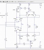
Front EndBut my question was: Is it new; has anybody seen it before?
Cheers,
E.
Mirror symmetry or camera playback ?Hi Ronny,
Please, show us how to do that without degrading the gain of the LTP-VAS combo (and without using a CMCL, of course).
Cheers,
E.
Do you mean somthing simple like this, far from optimal. Twisted mirror; 😉
Attachments
Don't want to beat a dead "TPC versus TMC" horse but the observation on TPC and Bode maximization is new AFAIK.
"Has anyone seen this feedback observation before?"
Dr Richard Mitchell's Selected Research Papers and Presentations
one of the few other places I've seen Bode's maximum Feedback discussed - and at least one paper goes a little sideways - probably was unaware of BJ Lurie's work
[..]
It is not difficult to design an IPS-VAS that is far better than the output stage, leaving the output stage to strongly dominate and ultimately limit the distortion performance of the amplifier.
[..]
Cheers,
Bob
Hi Bob,
I fully agree with that. Yet I can't resist to nitpick on one point, if you don't mind.
Strictly speaking, it's the IPS that ultimately limits the performance*, as the non-inverting half of this stage isn't (and can't be) enclosed within the global NFB loop.
edit: * Unless someone invents a zero error subtracter.
@Pete, thanks for the links.
Cheers,
E.
Last edited:
Is it wrong to go on from there and suggest that better matching of the input pair would maintain the LTP performance, even though half of it does not benefit from the distortion attenuation of the feedback?..........as the non-inverting half of this stage isn't (and can't be) enclosed within the global NFB loop...........
It also seems that using the more sophisticated front end topologies, eg cascoded input and Baxandall pair input would help improve the overall LTP performance, due to that lack of feedback to the non-inverting half.
one of the few other places I've seen Bode's maximum Feedback discussed
Some reading from Reading, how appropriate.
I don't think he actually says that TPC can approximate Bode maximum.
But nice work and thank you for the link.
Best wishes
David
TMC appears to lead to a superior implementation in the way it minimises the load on sensitive parts of the circuit.
TPC appears to have some theoretical possibility to increase the feedback.
On the dead forum Megajocke (using more of a "brute force" method, he also posted the details somewhere on diyaudio.com) and syn08 (using a canonical star-triangle circuit transformation of the TMC network) independently proved mathematically (and no, not by simulation!) that a TMC is, for all purposes, equivalent to a TPC plus a lead-lag compensation network. This equivalence should be understood in the sense that given a TMC compensated loop gain vs. frequency, then a TPC plus a lead lag compensation network can be calculated to provide mathematically exactly the same loop gain, at all frequencies. Anything else beyond this result is bedtime story.
Otherwise, TPC extra loads the VAS, TMC extra loads the input stage - pick your poison.
Hi Waly,
Theoretical proofs are indeed important, and provide insight, but they have their limitations. Whether or not this theory is correct, it must make assumptions about the implementation of the amplifier, and other assumptions to just make the problem tractable.
Simulation of a real amplifier design is closer to reality than theory, but it also has its limitations. Finally, building a real prototype is still a better indicator, but not necessarily the final word in the general case.
Your point about TMC "loading" the input stage probably refers to the fact that TPC provides more gain after the input stage than TMC, since for that aspect of analysis TMC behaves more like straight Miller compensation. Depending on the details of the amplifier design, some designers may be able to do better with TPC. My personal experience, based on many simulations of different amplifier designs, is that my outcome is better with TMC than with TPC when I do the best I can to optimize both, with stability of the two designs held reasonably constant in regard to overall fairness. Your mileage may differ.
If they are the same by adding a lead-lag network to TPC (presumably to flatten the closed loop response), why would anyone go for the extra complexity required to make TPC the same as TMC?
What counts for me is results that are obtainable in the real world with reasonable effort and reliability, not whether two approaches are theoretically the same.
I should also add that I am not a long-time detractor of TPC. I first used TPC in the late 1970's at Bell Labs in the design of operational amplifier ICs that were intended to allow the building of better active filters, such as for Biquad filters (BTW, Jimmy Tow worked for me). TPC was an important tool in making adequate operational amplifiers that had the limitation of slow lateral PNP transistors at the time.
Cheers,
Bob
Your point about TMC "loading" the input stage probably refers to the fact that TPC provides more gain after the input stage than TMC, since for that aspect of analysis TMC behaves more like straight Miller compensation.
If they are the same by adding a lead-lag network to TPC (presumably to flatten the closed loop response), why would anyone go for the extra complexity required to make TPC the same as TMC?
Yes, same thing.
The discussion went over time well beyond some implementation details. It was stated that TMC is "vastly superior", that it is "a first order system" so that's why it offers flat phase, that "it shines" over TPC, etc... etc... etc... But if we agree the only difference (other than personal taste) resides in the cost of a cap and a resistor, then I may concede TMC is superior.
It's probably to late for me to think straight, but your statement "simulation of a real amplifier design is closer to reality than theory" doesn't make any sense. Last time I've checked, simulation is theory, so it can't go against theory
 .
.I do think TMC may be oversold by some as more stable do to the "single pole" loop global response
measured inside both loops around the output devices TMC and TPC have to be designed to the same constraints, high frequency intercept region loop gain is near exactly same shape, if some people wouldn't use 2-pole on stability grounds they shouldn't use TMC
if they aren't competent to design 2-pole compensation, they also shouldn't play with TMC
I do think TMC may be oversold by some as more stable do to the "single pole" loop global response
measured inside both loops around the output devices TMC and TPC have to be designed to the same constraints, high frequency intercept region loop gain is near exactly same shape, if some people wouldn't use 2-pole on stability grounds they shouldn't use TMC
if they aren't competent to design 2-pole compensation, they also shouldn't play with TMC
Hi jcx,
You are right about the importance of evaluating and assuring stability of both loops in TPC and TMC designs. This was indeed done in the previous long and detailed postings on the matter in other threads. Assuring that those loops are equally stable in both TMC and TPC is important to a fair comparison. One cannot be complacent just because the global loop retains good phase and gain margins in TMC. However, the fact that TPC and TMC have the "same constraints" in this regard does not mean that the optimum design values of their compensation components are the same. Those who mistakenly set the component values the same will not get a proper comparison.
TMC may not be the answer to the maiden's prayer, and may have been a bit oversold, but it remains superior to TPC in my experience. There is no free lunch, but some choose a better diet than others.
Cheers,
Bob
Yes, same thing.
The discussion went over time well beyond some implementation details. It was stated that TMC is "vastly superior", that it is "a first order system" so that's why it offers flat phase, that "it shines" over TPC, etc... etc... etc... But if we agree the only difference (other than personal taste) resides in the cost of a cap and a resistor, then I may concede TMC is superior.
It's probably to late for me to think straight, but your statement "simulation of a real amplifier design is closer to reality than theory" doesn't make any sense. Last time I've checked, simulation is theory, so it can't go against theory
Hi Waly,
Have you simulated any amplifiers with both TMC and TPC compensation approaches?
Cheers,
Bob
TMC may not be the answer to the maiden's prayer, and may have been a bit oversold, but it remains superior to TPC in my experience.
Could you enumerate a few good reasons?
Have you simulated any amplifiers with both TMC and TPC compensation approaches?
Not sure which amplifiers you mean, but I have simulated a few Blameless type amplifiers in your book. For each TMC compensation network, I was able to find and optimize a TPC plus lead-lag compensation network that provides exactly the same loop gain and phase margin (as predicted by the theory). Obviously, the compensation network R and C values were different (who claimed they could be the same?).
Could you enumerate a few good reasons?
Not sure which amplifiers you mean, but I have simulated a few Blameless type amplifiers in your book. For each TMC compensation network, I was able to find and optimize a TPC plus lead-lag compensation network that provides exactly the same loop gain and phase margin (as predicted by the theory). Obviously, the compensation network R and C values were different (who claimed they could be the same?).
Hi Waly,
I think I have enumerated the reason I prefer TMC earlier, but the bottom line is that I have been able to get lower distortion out to high frequencies with TMC, without the disadvantage of a bump in the closed loop response and less phase margin in the global loop.
I earlier was led to believe that you were asserting that the closed loop frequency response of TPC could be made the same as that of TMC by adding a lead-lag network outside of the loop to straighten the frequency response. Please let me know if I was wrong. It was my impression that a simple first-order network could not make the TPC closed loop response identical to that of TMC. Let me know where you are placing the network and what it does, both for closed loop and open-loop behavior.
I'm glad to hear that you have simulated both TMC and TPC on the same amplifier. I don't think it matters which particular amplifier you are simulating it on unless some other shortcoming of the amplifier is large enough to mask the differences between TMC and TPC. For example, if you were using a very simple Blameless with only a Darlinton output, that might cloud the differences.
Mike was the one who insisted on using the same values of compensating components for TPC and TMC.
Please post your simulations of TPC and TMC on the same amplifier.
Cheers,
Bob
I earlier was led to believe that you were asserting that the closed loop frequency response of TPC could be made the same as that of TMC by adding a lead-lag network outside of the loop to straighten the frequency response.
Closed loop frequency response can be effectively made about the same
by adding an RC lead compensation from output to inverting input , wich amout to introduce
a zero in the transfer function ,but strictly speaking it is not the same thing as TMC.
Last edited:
[..]
if they aren't competent to design 2-pole compensation, they also shouldn't play with TMC
And if they aren't competent to design 1-pole compensation, they also shouldn't play with NFB. 😉
Cheers,
E.
I think I have enumerated the reason I prefer TMC earlier, but the bottom line is that I have been able to get lower distortion out to high frequencies with TMC, without the disadvantage of a bump in the closed loop response and less phase margin in the global loop.
I earlier was led to believe that you were asserting that the closed loop frequency response of TPC could be made the same as that of TMC by adding a lead-lag network outside of the loop to straighten the frequency response. Please let me know if I was wrong. It was my impression that a simple first-order network could not make the TPC closed loop response identical to that of TMC. Let me know where you are placing the network and what it does, both for closed loop and open-loop behavior.
Please post your simulations of TPC and TMC on the same amplifier.
- That would be incorrect. For whatever reason, you keep comparing TMC with pure TPC. The equivalent TPC and lead lag compensation has no bump and provides the same loop gain to lower the distortions. Again, the equivalence was proved mathematically, independent of any particular amplifier topology, by simply transposing the TMC network and calculating the new network (TPC + lead-lag) elements. For the exact math, you will have to contact megajocke and/or syn08.
- What made you think I have changed my mind? That was precisely my statement. I have never stated that TMC and pure TPC can provide exactly the same performance. They are close though, the lead lag network has mostly the purpose to provide the same phase characteristic as TMC.
- Will do.
Edit: We are way off topic and I already feel the love emanating from Amsterdam. We may continue this elsewhere, in another thread.
Last edited:
- That would be incorrect. For whatever reason, you keep comparing TMC with strictly TPC. The equivalent TPC and lead lag compensation has no bump and provides the same loop gain to lower the distortions. Again, the equivalence was proved mathematically, independent of any particular amplifier topology, by simply transposing the TMC network and calculating the new network (TPC + lead-lag) elements. For the exact math, you will have to contact megajocke and/or syn08.
- What made you think I have changed my mind? I have never stated that TMC and TPC can provide exactly the same performance. They are close though, the lead lag has mostly the purpose to provide the same phase characteristic as TMC.
- Will do.
Hi wahab,
I wasn't suggesting that you had changed your mind, I was just trying to get straight in my mind what it was that you were asserting when you stated that TMC was equivalent to TPC if a lead-lag network was added to TPC.
If I have got it straight now, you are just saying TPC then has no bump, but you are NOT saying that the closed loop frequency responses are exactly the same. Right?
Who wants to add a bandaid to TPC to make it almost the same as TMC? Why are you so stuck on TPC?
I'll look forward to seeing your simulations.
Cheers,
Bob
Hi wahab,
Cheers,
Bob
Bob , it seems that the TPC vs TMC debate is confusing ,
although not technicaly speaking...🙂
- Status
- Not open for further replies.
- Home
- Amplifiers
- Solid State
- Has anyone seen this front-end before?