I also find the comment about "ideal" matching to be rather odd for anyone with simulator and model experience. I've never seen models for N and P complementary types to be even close or any sort of idealized exact complements, rather they usually come from the data sheet reflecting the real and significant differences. Often one of the two is broken, lol! Then for any complaint about same type exact matching, we are able to get duals for many of these devices that are in reality quite close. Or we can try to get them from at least the same wafer in cases where matching is important - not suggesting that it is or not with your design just an observation on the previous comment.
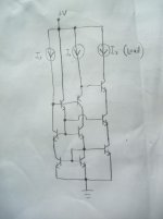
The circuit in post 318 is interesting. I think it may need a differential feedback loop and an input reference voltage in order to balance. I once used a Thompson mirror in a circuit to balance the common mode in a similar way; there are two current inputs to a Thompson mirror. I gave it up in favor of a different approach.
A Thompson-swap mirror.😉
A Thompson-swap mirror.😉
Attachments
Hi Edmond do you mind comment on more current gain in the vas stage as an alternative to an extra stage in the amplifier ?
Yes there vas some fighting issues in that stage.
Hi Ronny,
As promised, I've simulated your circuit. The collector current of the TIS is pretty stable over temperature. As the current gain of this stage is limited (16dB), you probably need to compensate for this by means of a pre driver or so.
If you don't mind, the common mode behavior is not yet optimal: R10 & R11 need to be increased from 72 to 77.9 Ohms in order to equalize the current gain from the base of Q10 to the output, respectively from the base of Q12 to the output. This is because the dynamic impedance at the emitter of Q1 is lower (Ic is higher) compared to the one of Q10.
Probably due to asymmetry of the current mirrors, CMRR is not that good: Above 10kHz it starts to drop. Maybe you can improve it by means of a 'clever' cap.
Cheers,
E.
Matching
Hi Pete,
I like to add that in case where tight matching is important, an experienced designer will always investigate how tight it must be, for example by looking at the effect of inserting a small (offset) voltage in series with the base.
In case of the AB2-OPS, indeed tight matching of the drain current sensing trannies is paramount. For this very reason I'm using THAT300 and THAT320 IC's. So the suggestion that I (might) have neglected these matching requirements is ridiculous, totally! On top of that, the suggestion came from someone who has published completely wrong simulation figures on this forum. That's what I meant by 'self-projection' (of his own level of experience onto someone else).
Cheers,
E.
I also find the comment about "ideal" matching to be rather odd for anyone with simulator and model experience. I've never seen models for N and P complementary types to be even close or any sort of idealized exact complements, rather they usually come from the data sheet reflecting the real and significant differences. Often one of the two is broken, lol! Then for any complaint about same type exact matching, we are able to get duals for many of these devices that are in reality quite close. Or we can try to get them from at least the same wafer in cases where matching is important - not suggesting that it is or not with your design just an observation on the previous comment.
Hi Pete,
I like to add that in case where tight matching is important, an experienced designer will always investigate how tight it must be, for example by looking at the effect of inserting a small (offset) voltage in series with the base.
In case of the AB2-OPS, indeed tight matching of the drain current sensing trannies is paramount. For this very reason I'm using THAT300 and THAT320 IC's. So the suggestion that I (might) have neglected these matching requirements is ridiculous, totally! On top of that, the suggestion came from someone who has published completely wrong simulation figures on this forum. That's what I meant by 'self-projection' (of his own level of experience onto someone else).
Cheers,
E.
Last edited:
Hi Andrew,
As a matter of fact, the TIS does suffer from a tiny bit of sticking. Maybe it also contributes to the ringing. I have to check it out. If so, I'll add a Baker clamp.
Cheers,
E.
edit: Indeed, a Baker clamp helps a bit. The amplitude of ringing becomes about 50% smaller.
Now, I have to figure out a clamp that doesn't contribute to distortion.
Edmond, I used a BAV21 - reverse capacitance at low voltages is only a couple of pF so there's not much contribition to VAS non-linearity due to modulation of the junction capacitance with voltage.
Edmond, I noted your earlier comment about Bob Cordell's HEC ULGF of 3MHz. You can only do that with Mosfets! With the 1302/1281 bipolars I think 1.5MHz might be possible, but I have settled on c. 1MHz leaving about 85 deg of p.m. and lots of gain margin.
Detials will be up in the next 2 weeks.
Detials will be up in the next 2 weeks.
Edmond, I used a BAV21 - reverse capacitance at low voltages is only a couple of pF so there's not much contribition to VAS non-linearity due to modulation of the junction capacitance with voltage.
Hi Andrew,
Perhaps a BAV21 does a perfect job in other amps, but not in this case.
I'm sorry I have to disappoint you, but even with the BAV21's, THD20k (of the SuperTis alone) rises from 56ppb to 2.4ppm

So a more complex solution is really needed, as sown on page 317.
Cheers,
E.
Edmond, I noted your earlier comment about Bob Cordell's HEC ULGF of 3MHz. You can only do that with Mosfets! With the 1302/1281 bipolars I think 1.5MHz might be possible, but I have settled on c. 1MHz leaving about 85 deg of p.m. and lots of gain margin.
Details will be up in the next 2 weeks.
I suppose (well, I'm pretty sure) because MOSFETs are faster.
This is one reason I prefer MOSFETs.
On the other hand, a BJT distorts less, so decreasing the ULFG of the HEC loop to 1MHz will probably yield equal THD figures.
Cheers,
E.
BAV21 Crev is c. 1.2pF IIRC al low voltages. You are going to have a lot of parasitic capacitances around the VAS stage up to 10x this level.
Err.....a lot of parasitic capacitances ? Not that I know of.
The reason that most people think the BAV is so good might be that in 'normal' amps 2.4ppm distortion from the clamp is completely masked by other distortion mechanisms.
Cheers,
E.
The reason that most people think the BAV is so good might be that in 'normal' amps 2.4ppm distortion from the clamp is completely masked by other distortion mechanisms.
Cheers,
E.
Edmond, I noted your earlier comment about Bob Cordell's HEC ULGF of 3MHz. You can only do that with Mosfets! With the 1302/1281 bipolars I think 1.5MHz might be possible, but I have settled on c. 1MHz leaving about 85 deg of p.m. and lots of gain margin.
Detials will be up in the next 2 weeks.
Hi Bonsai,
You are exactly right about the role played by MOSFETs in the HEC circuit I used. They are intrinsically much faster than BJTs and permit fairly wideband local feedback. The equivalent ft of the MOSFETs is generally over 100 MHz.
Cheers,
Bob
Err.....a lot of parasitic capacitances ? Not that I know of.
The reason that most people think the BAV is so good might be that in 'normal' amps 2.4ppm distortion from the clamp is completely masked by other distortion mechanisms.
Cheers,
E.
Use the Flying Baker Clamp described in my book on page 193 and this will not be an issue.
Cheers,
Bob
clamp
Many thanks Bob for the hint. I will also evaluate the Flying Baker Clamp and compare the results with this clamp
Cheers,
E.
Use the Flying Baker Clamp described in my book on page 193 and this will not be an issue.
Cheers,
Bob
Many thanks Bob for the hint. I will also evaluate the Flying Baker Clamp and compare the results with this clamp
Cheers,
E.
It was long shown (and even the reviver of TMC now seem to admit) that all being equal, TMC and other 2 DOF techniques (like two pole) allow the same amount of loop gain.
To put it simply, given a single pole open loop gain with a crossover frequency of F, the only way to squeeze out more loop gain at HF is to use N poles to roll of the gain before F and to add N-1 zeros to bring back the phase to the stability condition. Unfortunately, that barely works for N larger than 2, other than in theory, because of very practical reasons related to circuit sensitivity. Or even simpler put, a three gain stage amplifier is very difficult to compensate and stabilize. Cherry compensation used in PGP is the only notable exception that I am aware of.
Now, there are ways to further optimize multiple embedded loops, but they are so mind boggling I couldn't even think of a practical implementation in discrete circuits. Strictly speaking, a multiloop system doesn't have to have each and every feedback loop stable. All that it matters is the total number of circles around the critical point, in the phase space. That is, internal and external unstable loops can help each other to get an overall stable system. Here's an old article about this, now try and implement such a circuit with discretes 😀.
But enough of this - have fun and don't forget to build your dreams!
At last; someone who knows what he's talking about. Take note, Edmond!
Use the Flying Baker Clamp described in my book on page 193 and this will not be an issue.
Cheers,
Bob
Hi Bob,
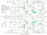
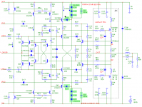
I finally succeeded to implement stable clamps and the solution appears to be very simple: just use 'brute force' clamps and flying catching diodes. The Baker clamp as shown on page 317 wasn't stable, because the loop gain (of the clamp) wasn't controlled by Cdom (Cdom stays outside the loop). As a result, the phase margin was close to zero. Brute force clamps don't suffer from these issues and are permitted in this amp, because the CCSes limit the clamping current to modest values anyhow.
The highlighted components in the pictures below, depict the 'brute force' clamps, while D8 & R38 respectively D9 & R39 prevent entering nonlinear currents from D3 respectively D4 into the very sensitive nodes A and B.
The 'flying catching' diodes are: D14, D15, D18 and D19.
Cheers,
E.
Attachments
Last edited:
The initial comments in post #333 about equivalence of TPC and TMC appear to be taken from Ovidiu Popa's site where he references DIY-audio-engineering.org. The site has been taken down. Does anyone have a copy of the discussion?
Best wishes
David
Best wishes
David
The initial comments in post #333 about equivalence of TPC and TMC appear to be taken from Ovidiu Popa's site where he references DIY-audio-engineering.org. The site has been taken down. Does anyone have a copy of the discussion?
Best wishes
David
Without wanting to derail the thread , although TMC and TPC
share some similarities they are not strictly equivalent unless
limit cases are took into account such as shorting the output
to ground , in wich case it would yield strictly the same system.
... TMC and TPC share some similarities they are not strictly equivalent unless limit cases....
Thank you Wahab, this is also my belief and I would like to confirm or disprove it.
One of your posts about DIY_Audio_engineering implies you read it.
Do you remember who posted the analysis?
I think this relevant to help understand Edmond's front end circuit but PM me if you think it's off-topic.
Best wishes
David
Its interesting to see the matter of TPC and TMC come up again. It was pretty thoroughly discussed in some other threads previously.
While Waly's reminder about the stability limitations shared by TMC and TPC is correct, it is important to bear in mind that TPC and TMC are not the same. Some are perhaps misled by their topological similarity of appearance to think they are equivalent and even that they are each optimized with the same component values.
TPC and TMC are not the same. I believe that TMC has important advantages, even though it is not a silver bullet that enables one to enclose the output stage with more feedback at high frequencies. First, TMC makes the global feedback loop first order, just like conventional Miller compensation. It does not create closed-loop frequency response peaking like TPC does, and it does not reduce the phase margin of the global loop in the way that TPC does.
Secondly, TMC does not load the VAS as much as TPC, since the shunt resistor is bootstrapped over the majority of the frequency range by the output stage.
Of course, one must be mindful of the stability of the combined loops surrounding the output stage, and this is where TMC and TPC must abide by some of the same rules and limitations. This does not mean that their effectiveness in reducing the distortion in a real amplifier must be the same.
TPC encloses all three stages (IPS, VAS, OPS) in a second-order loop, while TMC encloses only the VAS and output stage in the more complex loop. Some will say that this is a disadvantage of TMC, not including the IPS. However, the real elephant in the room in well-designed amplifiers is the output stage. It is not difficult to design an IPS-VAS that is far better than the output stage, leaving the output stage to strongly dominate and ultimately limit the distortion performance of the amplifier.
The OPS is where most of the distortion action is and that is what needs the most help from either TPC or TMC. The fact that the complex loop in TMC encloses one less stage may allow more effective feedback enclosing the output stage because excess phase contributed by the IPS is not in that loop.
Some have compared TMC and TPC using the same values of C1, C2 and R, and concluded that TMC is no better. This is a flawed approach. The optimum component values for TPC and TMC are different. When each is examined in simulation with its optimum component values, and the net stability of the enclosure of the output stage is kept the same, it is my experience that TMC is superior.
Edmond did not come up with TMC, and he will be the first to say that. However, he deserves a lot of credit for popularizing it. Edmond is the person from whom I learned about TMC. It is also notable that Doug Self did not publish anything about TMC until after Edmond popularized it.
Cheers,
Bob
Its interesting to see the matter of TPC and TMC come up again. It was pretty thoroughly discussed in some other threads previously.
... (much helpful stuff snipped)
Cheers,
Bob
Yes, I have read most of the old threads and it has certainly been discussed exhaustively😉 here. Edmond's new circuit is intended to be "rid of the cons and keep the pros of both techniques" so that's why it has come up once more. I take it that the DIY_audio_engineering thread was a continuation of the discussion here so I hoped it would be more conclusive.
Is it possible to obtain a copy?
I believe you are a close friend of the site builder, would he be prepared to put the material on DiyAudio?
Thank you for the very sensible summary.
Best wishes
David
Hi Bob,
As you said:
>"TPC encloses all three stages (IPS, VAS, OPS) in a second-order loop, while TMC encloses only the VAS and output stage in the more complex loop. Some will say that this is a disadvantage of TMC, not including the IPS." (Mike KS for example) , and:
>"TMC does not load the VAS as much as TPC, since the shunt resistor is bootstrapped over the majority of the frequency range by the output stage."
This is the reason (according to me) why in real amplifiers TMC and TPC yield similar distortion figures.
BTW1, the graphs of fig.2 on my website nicely illustrate the VAS loading by TMC vs TPC.
>Some have compared TMC and TPC using the same values of C1, C2 and R, and concluded that TMC is no better. This is a flawed approach. The optimum component values for TPC and TMC are different.
Exactly!
BTW2, some 'expert' on this subject even claims that the capacitor ratio of C1 and C2 is 'irrelevant'. 🙄
Why?! Just copy & paste knowledge from some obsolete textbook.😕
Cheers,
E.
- Status
- Not open for further replies.
- Home
- Amplifiers
- Solid State
- Has anyone seen this front-end before?