Harry's "Dayton soundbar"
Hello DiyAudio forumites, this is my first post on here... G'day from Australia 😀
Im looking at building and BT soundbar/boombox for my metalwork/car workshop, it needs to get reasonably loud and sound nice(better than a cheap plastic thing).
I've done a little bit of speaker building before and done a few car audio installations in the past(My own and mates systems, full custom builds) and I'm also into making furniture, so physically constructing them is no problem.
I have already purchased my drivers and amp they are,
Dayton ND25FW-4 for the highs
Dayton RS180-4 for mid/mid-bass
Dayton RSS265HF-4 for the low end
Dayton DTA-2.1BT2 amp
I was intending to make a large "Dayton" soundbar all in one solution that can be used for my workshop of course and occasionally for party background music so some portability is desired... even if it takes two to carry it🙄
As you would guess by my driver list its going to be a 2 way with sub, I will need some direction on the xovers for the ND25FW-4 and RS180-4, Im trying to learn as much as I can on them so far I think a xover around the 3k point, Dayton suggest keeping above 2.5k for the ND25FW.
I've tried to model the xovers in the excel sheet by JB after following Toid123's tutorial on YT, still playing around with it so I will have some questions to ask later when I go to finalise them as Id rather complete the box design first so I can include a bafflestep correction.
The box(s) design so far I have used Winisd and come up with,
Sub box vol is 50ltrs double slot ported @30Hz
Mid boxes vol is 15.4ltrs single slot ported @44Hz
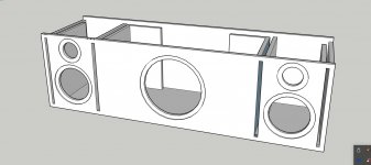
The design is a box 300x300x675mm internally for the sub and 300x300x203mm for the mids, these volumes include vol for drivers ports and some bracing.
So here's my 1st question, looking at the picture below you can see its going to be sumo sized soundbar at about 350x350ish mm by around 1200mm long(14x14x48" approx), as all the drivers are on the same baffle how will this effect bafflestep and will it cause any bad cancellations? Is this design a bad idea can you see any major problems with box design and/or driver selection?
Hello DiyAudio forumites, this is my first post on here... G'day from Australia 😀
Im looking at building and BT soundbar/boombox for my metalwork/car workshop, it needs to get reasonably loud and sound nice(better than a cheap plastic thing).
I've done a little bit of speaker building before and done a few car audio installations in the past(My own and mates systems, full custom builds) and I'm also into making furniture, so physically constructing them is no problem.
I have already purchased my drivers and amp they are,
Dayton ND25FW-4 for the highs
Dayton RS180-4 for mid/mid-bass
Dayton RSS265HF-4 for the low end
Dayton DTA-2.1BT2 amp
I was intending to make a large "Dayton" soundbar all in one solution that can be used for my workshop of course and occasionally for party background music so some portability is desired... even if it takes two to carry it🙄
As you would guess by my driver list its going to be a 2 way with sub, I will need some direction on the xovers for the ND25FW-4 and RS180-4, Im trying to learn as much as I can on them so far I think a xover around the 3k point, Dayton suggest keeping above 2.5k for the ND25FW.
I've tried to model the xovers in the excel sheet by JB after following Toid123's tutorial on YT, still playing around with it so I will have some questions to ask later when I go to finalise them as Id rather complete the box design first so I can include a bafflestep correction.
The box(s) design so far I have used Winisd and come up with,
Sub box vol is 50ltrs double slot ported @30Hz
Mid boxes vol is 15.4ltrs single slot ported @44Hz
The design is a box 300x300x675mm internally for the sub and 300x300x203mm for the mids, these volumes include vol for drivers ports and some bracing.
So here's my 1st question, looking at the picture below you can see its going to be sumo sized soundbar at about 350x350ish mm by around 1200mm long(14x14x48" approx), as all the drivers are on the same baffle how will this effect bafflestep and will it cause any bad cancellations? Is this design a bad idea can you see any major problems with box design and/or driver selection?
Attachments

Last edited:
Uh, the RS180-4 may not like the 2.5-3k xover requirement, as they like to be xoverd lower than that to avoid the breakup. If you use the RS180P-4, you'll be okay.
Later,
Wolf
Later,
Wolf
The design looks pretty good to me.
IMO, you should be able to dial this in to work fine in a workshop.
To me, the main oddity is that the 7" drivers are capable of playing quite low AND your plan shows them in ported enclosures. If you do this, the 12" sub is superfluous.
The 7" enclosures, as described (18 litres, ported) might have a bit of "boom" - which might be a good thing, depending on your tastes and goals.
Have you planned it this way?
Me, I'd consider constructing it with the 7" drivers sealed, and the 12" ported.
You could shrink the Dayton RS180-4 enclosures down to 10 or 12 litres, and set the Dayton RSS265HF-4 crossover to about 65Hz.
Notes:
If you get it sounding perfect in your workshop, then take it somewhere else for party use (big spaces / open air), the sound balance will change a lot.
It's hard to get loud low end when outdoors. If you are used to car sound work, the difference might surprise you.
Build ideas:
Check out the "boominator" (the DIY thread, or just do an image search) for design ideas you can steal. Many examples have been built.
Think about portability before you start building - you probably have a dolly or something that would let you move it around solo. Putting a strap attachment point on one end, and grip tape on the underside, could make it pretty easy to tow around on a dolly.
If you can add some sort of equalisation, you can get away with a much simpler crossover.
If you build it, and it sounds bad, the first thing I'd try is changing positioning - try it on the floor, raised up off the floor, close to a corner, far from all corners, etc.
Wolf_Teeth you are probably right should have gotten the paper versions(they were cheaper too...), but I already have them... the old hindsight😱
I was looking at the cone breakup on the RS180-4 seemed to start dropping off at 3.4kHz and going to a high peak at around 6KHz. With this in mind would a high order xover around 3kHz help to create a steeper roll off to hide the cone break up?
hollowboy, yes the initial idea was to have the 7" sealed with the 10" ported, but when I started play with Winisd they seem to model better in a ported box. They will have a more useable lower extension using less power(Only got 50W to play with)and will allow me to xover the sub lower or have an impressive lower mid bass kick using less watts. I listen to mostly rock/blues/Funk and metal... love nice punchy midbass.
Boominator... wish I knew that search term before
Portability will be ok, if she's too heavy I'll carry it with me tractor's FEL bucket 😀. Yes do realise bass can disappear in open big air spaces, even noticed after shifting to our new place with my old HT sub(Adire Shiva MkII 12" 110ltr ported @24hz)the old room was 4x5m and the new is 12x8m I ended up cranking up the gain a fair bit its still not as loud and I can hear it stressing out which I think its the amp distorting. That will be a future project prob need a pair of UM18's!
The kind places this boombox will get used for are outdoors but under our pergola area(its semi a enclosed area)and in our rock'n'roll themed B&B when the boys are over for cards darts n billiard nights we have a rural property and can make lots of noise!
Its not going to be real portable anyway needs a wall outlet no battery's involved😱
I was looking at the cone breakup on the RS180-4 seemed to start dropping off at 3.4kHz and going to a high peak at around 6KHz. With this in mind would a high order xover around 3kHz help to create a steeper roll off to hide the cone break up?
hollowboy, yes the initial idea was to have the 7" sealed with the 10" ported, but when I started play with Winisd they seem to model better in a ported box. They will have a more useable lower extension using less power(Only got 50W to play with)and will allow me to xover the sub lower or have an impressive lower mid bass kick using less watts. I listen to mostly rock/blues/Funk and metal... love nice punchy midbass.
Boominator... wish I knew that search term before
Portability will be ok, if she's too heavy I'll carry it with me tractor's FEL bucket 😀. Yes do realise bass can disappear in open big air spaces, even noticed after shifting to our new place with my old HT sub(Adire Shiva MkII 12" 110ltr ported @24hz)the old room was 4x5m and the new is 12x8m I ended up cranking up the gain a fair bit its still not as loud and I can hear it stressing out which I think its the amp distorting. That will be a future project prob need a pair of UM18's!
The kind places this boombox will get used for are outdoors but under our pergola area(its semi a enclosed area)and in our rock'n'roll themed B&B when the boys are over for cards darts n billiard nights
we have a rural property and can make lots of noise! Its not going to be real portable anyway needs a wall outlet no battery's involved😱
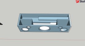
Still playing with box designs, after reading up on porting I've decided to not use such skinny slot ports with sharp bends on the sub and use the KISS theory changed to round ports, staying with 50ltrs@30Hz
And KISS theory again on the midbass drivers going sealed @ 10ltrs, this allowed fitting the long ports in for the sub(@718mm L 86.6mm ID).
If you look at the Sketchup design below you can see I've put the ports at opposite ends to each other but at a vertical offset to allow the lengths to pass each other inside the box, this also allows for a brace running full length end to end also bracing the back of the mid bass enclosures at the same time.
The pictures dont show the flares at each end of the ports or the bracing that will hold the ports in place.
I will router the outer flares using a 1 1/4" roundover bit and the inside ones I will make on my lathe.😎
Looking at my placement of the mid and tweeter is it a bad idea to have them offset or would it be better being centred vertically? Im unsure I cant seem to find anyone who has done any real research on a soundbar designs regarding SQ wise, ie having all the drivers left/right and sub all on the same baffle? How much difference is made in driver placement and or port placement?
Still playing with the Xover design, the cone break up on the RS180-4's is hard to deal with, seems its going to be a complicated scenario I will put up what I have come up with in the next few days... I can only go by Daytons data files not measured 1st hand.
Almost thinking to go 3way and include a midrange to xover the 180's a lot lower... hmmm more coin🙄
Attachments

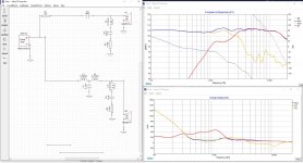
This is what I've come up with so far for the 2way xovers, is there anything blazingly obvious Im missing.
I've looked at every graph in Xsim particularly the current Rms the highest value is the R1 on the tweeter which is 4A rms@100w(these speakers will be driven by 50wrms).
I've looked at every graph in Xsim particularly the current Rms the highest value is the R1 on the tweeter which is 4A rms@100w(these speakers will be driven by 50wrms).
Attachments
Some XSim critiques:
- turn off system phase and turn on driver phase
- extract minimum phase from your files, in the 'Tune' window choose 'derived' for both frd and zma files. You need to extend the tails for the frd files when you do so.
- you need to account for the relative difference between the 2 drivers' acoustic centers. It's more or less an educated guess without doing real measurements, maybe somewhere between .5" and 1". I put in .75" in the woofer 'delay' box, again in the 'Tune' window.
- baffle effects should also be included in the frd files. Baffle step loss will depend on where you position the unit, on a table up against a wall vs out in free space. Otherwise the xo lacks accuracy.
Some xo critiques:
- tweeter and mid are not well matched as Wolf said, the tweeter wants to be crossed high and the woofer wants to be crossed low. The only way to make them work well enough is to go higher order acoustic slopes.
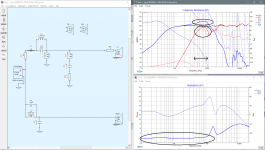
- looking at your xo (pic 1), I've circled the most egregious parts
- between about 1kHz and 9kHz, you have a noticeable rise in the FR
- woofer break up and resonances are only down about 20-25dB
- tweeter resonance at 1350Hz is only down about 10dB, even worse
- phase is not well aligned in the xo region as you can tell by the lack of a reverse null at the xo frequency (grey curve)
- in the Current chart, you have some inefficiency centered at about 2500Hz due to your 2 notch filters which I'm not sure are doing exactly what you want them to, but the inefficiency isn't actually that bad.
Pic 2 is not to be taken as correct but it should give you a better idea of how to attack your problems.
- acoustic slopes are increased via 4th order electrical filters so now cone breakup and tweeter resonance are much further down in SPL.
- C6 on the woofer acts as a notch filter to further help bring the woofer breakup under control.
- the real parallel notch filter is aimed at a peak at about 1700Hz on the woofer.
- C3 on the tweeter helps to tame a rising response in the highest frequencies.
- phase is now well aligned in the xo region with a good reverse null, grey curve again.
The biggest negative is in the Current chart where the inefficiency is worse than your 1st xo. But this is the price you may have to pay to work with these drivers. Trying to force them to do something they really don't want to means that the shunt capacitors (on the woofer) sometimes have to be bigger and/or the shunt inductors (on the tweeter) have to be smaller than ideal. These can create more current running to ground than running to the drivers sometimes. Not the end of the world if your amp can handle it but again, not ideal.
Hope that helps. Personally I think I would be looking at a different tweeter that will be happy crossed lower (Fs closer to 600Hz) before I would start thinking about turning the L and R into 3-ways. Look at SB Acoustic tweeters in particular. Smaller face plates would help you too. My XSim is attached.
- turn off system phase and turn on driver phase
- extract minimum phase from your files, in the 'Tune' window choose 'derived' for both frd and zma files. You need to extend the tails for the frd files when you do so.
- you need to account for the relative difference between the 2 drivers' acoustic centers. It's more or less an educated guess without doing real measurements, maybe somewhere between .5" and 1". I put in .75" in the woofer 'delay' box, again in the 'Tune' window.
- baffle effects should also be included in the frd files. Baffle step loss will depend on where you position the unit, on a table up against a wall vs out in free space. Otherwise the xo lacks accuracy.
Some xo critiques:
- tweeter and mid are not well matched as Wolf said, the tweeter wants to be crossed high and the woofer wants to be crossed low. The only way to make them work well enough is to go higher order acoustic slopes.
- looking at your xo (pic 1), I've circled the most egregious parts
- between about 1kHz and 9kHz, you have a noticeable rise in the FR
- woofer break up and resonances are only down about 20-25dB
- tweeter resonance at 1350Hz is only down about 10dB, even worse
- phase is not well aligned in the xo region as you can tell by the lack of a reverse null at the xo frequency (grey curve)
- in the Current chart, you have some inefficiency centered at about 2500Hz due to your 2 notch filters which I'm not sure are doing exactly what you want them to, but the inefficiency isn't actually that bad.
Pic 2 is not to be taken as correct but it should give you a better idea of how to attack your problems.
- acoustic slopes are increased via 4th order electrical filters so now cone breakup and tweeter resonance are much further down in SPL.
- C6 on the woofer acts as a notch filter to further help bring the woofer breakup under control.
- the real parallel notch filter is aimed at a peak at about 1700Hz on the woofer.
- C3 on the tweeter helps to tame a rising response in the highest frequencies.
- phase is now well aligned in the xo region with a good reverse null, grey curve again.
The biggest negative is in the Current chart where the inefficiency is worse than your 1st xo. But this is the price you may have to pay to work with these drivers. Trying to force them to do something they really don't want to means that the shunt capacitors (on the woofer) sometimes have to be bigger and/or the shunt inductors (on the tweeter) have to be smaller than ideal. These can create more current running to ground than running to the drivers sometimes. Not the end of the world if your amp can handle it but again, not ideal.
Hope that helps. Personally I think I would be looking at a different tweeter that will be happy crossed lower (Fs closer to 600Hz) before I would start thinking about turning the L and R into 3-ways. Look at SB Acoustic tweeters in particular. Smaller face plates would help you too. My XSim is attached.
Attachments

Thanks jReave much appreciated you given me much to ponder.
I think I will have to admit defeat and obtain some different drivers, given the extra cost and availability of a good low Fs tweeter its gunna be cheaper(on this project)and do as Wolf said and grab some RS180P-4 or similar as they are cheaper than tweeters + double the xover parts and I only have 50w to drive them so efficiency is important
I'll save the RS180-4's for another project(a 3way centre speaker maybe I'll xover them at 500Hz or something)
I'll design a new xover and do some learning on your Xsim suggestions, the baffle step considerations will be near impossible to work out, being a speaker for my car/metal workshop and for occasional party background it'll get shifted around somewhat.
If it was me and I had the parts hanging around, I would actually give the xo a try and see how it sounded. Well 1st I'd do the sims over again with files that included all the right info. There's more than a few parts to go 4th order but they are all mostly small values so aren't very expensive. And I don't think you're looking for super high fidelity here so it might be ok. But not a great idea if you are on a budget and don't have xo parts laying around.
Otherwise do the sims 1st before buying anything else. The paper RS180 definitely lacks the resonant peaks of the metal version but it doesn't look that much happier crossing higher either.
And include the baffle diffraction sims. It's not too hard to simulate. In fact I just had a quick look and given the very large width of your front baffle (48"), it might actually be simpler than usual. Such a wide width means the baffle step loss occurs much lower in frequency, so much so that you may be able to simply adjust for the different placement scenarios with the sub level and xo point. By which I mean when it's up against a wall, cross the sub low (~60Hz?) and set the favored SPL level. When out in free space, raise the xo frequency up to maybe 150-200Hz and turn the sub up 3-6dB or whatever sounds best to you.
For baffle diffraction:
Tolvan Data
Loudspeaker Design Software - needs Excel though
I just had a look at 1 Aussie supplier - The Loudspeaker Kit - and found the Dayton RS180's to be more expensive than several SB tweeters that should work much better with the RS180-4:
SB26STAC-C000-4 - SB ACOUSTICS 1" DOME TWEETER - STAC - SB Acoustics
SB29RDC-C0004 - SB ACOUSTICS 11/4" RING TWEETER - RDC - SB Acoustics
SB29RDNC-C0004 - SB ACOUSTICS 11/4" RING TWEETER - RDNC - SB Acoustics
SB26STAC-C000-4 - SB ACOUSTICS 1" DOME TWEETER - STAC - SB Acoustics
SB29RDC-C0004 - SB ACOUSTICS 11/4" RING TWEETER - RDC - SB Acoustics
SB29RDNC-C0004 - SB ACOUSTICS 11/4" RING TWEETER - RDNC - SB Acoustics
LSK and their parent company WES are the only suppliers in AUST, yes I did spot them but I cant find any Frd or ZMA files for them so it makes it near impossible for me to model in Xsim. I dont really want to invest in a measurement set up and then learning how to do it(not just yet maybe later, I got way to many hobbies as it is!).
I also found these Wavecore tweeters
Even if I do change the tweeter theres still the problem of a reasonably complex xover to fix the RS180-4 cone break up in a 2way system, where as changing the woofer to something more friendly will simplify the xover I hope.
Plus I'd like to keep in all Dayton if possible, if the RS180p-4 doesnt model well the RS150P-4A could be a candidate.
Tracing FR and impedance curves is easy: FPGraphTracer : fprawn labs
You do have an advantage with Dayton though as their curves are known to be pretty accurate. But SB is pretty reliable as well. Double checking with 3rd party measurements doesn't hurt though if there is any doubt.
That Wavecore tweeter would do the trick as well.
With the RS180's, if the xo is low enough, it doesn't have to be super complex. Here's just an example with the RS180-8's in an MTM by Jeff Bagby - My RS180 MTM Design -
Techtalk Speaker Building, Audio, Video Discussion Forum - that's 3 components on the tweeter and 3 on the woofers.
The RS150P-4 certainly looks like a better match with your Dayton tweeter. You may need to protect the bottom end cone excursion with a large series capacitor because I think your amp only rolls of the sub and not the L and R speakers if you plan on playing them loud.
Good, I think looking at a better suited tweeter is a good idea.
Probably the 2 biggest obstacles to accuracy for beginners are not including baffle diffraction as well as not including the woofer delay due to the differences in the acoustic centers of the drivers and their respective positions on your baffle. The 3rd most common error is not deriving phase for the copied frd and xma files which is not the case here. Nice.
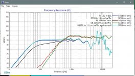
To solve the 1st problem, I've attached some new files for you below. For baffle diffraction, I put the tweeter 6" from the side and 11" from the bottom and the woofer 6" from the side and 5" from the bottom on a 48" x 14" front baffle. For the woofer, the 1st file is correct when the unit will be out from boundary walls and the 2nd file is with the unit right up against the rear wall so with baffle diffraction but with 6dB of boundary gain in the LF's. Technically the response is not 100% accurate because there will be a 2 to 3dB null in the LF's (maybe around 300Hz) too depending on the distance to the wall and then distance to the listener, but good enough for simulation purposes here. The attached pic just shows all the different responses together.
For acoustic centers with tweeters, the rule of thumb for a standard tweeter is at the bottom of the faceplate, so about 4mm back. For the woofer, the rule of thumb is at about where the voice coil meets the cone, most commonly where the spider is. Measuring from the spec sheet diagram, that's about 30mm back. So the difference in acoustic centers is about 26mm. When you take into account about a 6" height difference between the drivers and a 2-3m listening distance, the woofer delay works out to about 1" to 1.4". Unfortunately, this rule of thumb is often incorrect and the acoustic center of some drivers is actually more forward (one needs real measurements for the correct determination) so I would suggest using the smaller distance of 1" to start off with.
It looks to me like you are getting a better handle on the xo sims. Now it's just a matter of refining your technique and learning a few more tricks. I've included a new XSim below with the new files included, with 1" woofer delay and with some target curves. The target curves are great starting points as you work the component values. I chose 2nd order acoustic slopes crossing at 1800Hz. Go into the 'Curve' menu and choose '(driver only)' for S3 and S4. I like them in grey as it's not too distracting. Remember they are just targets and can be altered and turned off if desired.
I've got the feeling from you that you want to learn xo's so instead of just giving you what I might come up with, I've attached XSim with the components I'd use but with all the values still incorrect. Have at her and have fun.
Some other tips:
- your target SPL level should be your woofer level at about 200Hz. Bring the rest of the response down to that level and then match the tweeter as well.
- try to let the 1st series component do as much of the work as you can.
- I often use series resistors on the tweeter both before and after the filter - they have slightly different effects.
- the 2 trouble spots with this design are the tweeter resonance at 600Hz and the woofer resonances up above 7kHz. I would try to get each of those as far down from the fundamental as possible, up to 40dB if you can. L2 and C4 are little tricks to get those 2 tasks accomplished.
Probably the 2 biggest obstacles to accuracy for beginners are not including baffle diffraction as well as not including the woofer delay due to the differences in the acoustic centers of the drivers and their respective positions on your baffle. The 3rd most common error is not deriving phase for the copied frd and xma files which is not the case here. Nice.
To solve the 1st problem, I've attached some new files for you below. For baffle diffraction, I put the tweeter 6" from the side and 11" from the bottom and the woofer 6" from the side and 5" from the bottom on a 48" x 14" front baffle. For the woofer, the 1st file is correct when the unit will be out from boundary walls and the 2nd file is with the unit right up against the rear wall so with baffle diffraction but with 6dB of boundary gain in the LF's. Technically the response is not 100% accurate because there will be a 2 to 3dB null in the LF's (maybe around 300Hz) too depending on the distance to the wall and then distance to the listener, but good enough for simulation purposes here. The attached pic just shows all the different responses together.
For acoustic centers with tweeters, the rule of thumb for a standard tweeter is at the bottom of the faceplate, so about 4mm back. For the woofer, the rule of thumb is at about where the voice coil meets the cone, most commonly where the spider is. Measuring from the spec sheet diagram, that's about 30mm back. So the difference in acoustic centers is about 26mm. When you take into account about a 6" height difference between the drivers and a 2-3m listening distance, the woofer delay works out to about 1" to 1.4". Unfortunately, this rule of thumb is often incorrect and the acoustic center of some drivers is actually more forward (one needs real measurements for the correct determination) so I would suggest using the smaller distance of 1" to start off with.
It looks to me like you are getting a better handle on the xo sims. Now it's just a matter of refining your technique and learning a few more tricks. I've included a new XSim below with the new files included, with 1" woofer delay and with some target curves. The target curves are great starting points as you work the component values. I chose 2nd order acoustic slopes crossing at 1800Hz. Go into the 'Curve' menu and choose '(driver only)' for S3 and S4. I like them in grey as it's not too distracting. Remember they are just targets and can be altered and turned off if desired.
I've got the feeling from you that you want to learn xo's so instead of just giving you what I might come up with, I've attached XSim with the components I'd use but with all the values still incorrect. Have at her and have fun.
Some other tips:
- your target SPL level should be your woofer level at about 200Hz. Bring the rest of the response down to that level and then match the tweeter as well.
- try to let the 1st series component do as much of the work as you can.
- I often use series resistors on the tweeter both before and after the filter - they have slightly different effects.
- the 2 trouble spots with this design are the tweeter resonance at 600Hz and the woofer resonances up above 7kHz. I would try to get each of those as far down from the fundamental as possible, up to 40dB if you can. L2 and C4 are little tricks to get those 2 tasks accomplished.
Attachments
I had a play around with the base you gave me, I think I managed to get it somewhat ok.
I ended up shorting C1 it seemed to help smooth the FR between 600~1800Hz and I applied a shunt notch to flatten around 1400~2200Hz.
I think to get rid of the RS180-4 severe cone break up completely you would need to xover below 1kHz probably with a 3rd order or higher?
I ended up shorting C1 it seemed to help smooth the FR between 600~1800Hz and I applied a shunt notch to flatten around 1400~2200Hz.
I think to get rid of the RS180-4 severe cone break up completely you would need to xover below 1kHz probably with a 3rd order or higher?
Attachments
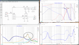
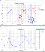
You are doing quite well at getting a flat FR in your sims. However you also need to achieve at least a couple of other things at the same time to get a satisfactory result. That's what can make it so challenging sometimes. Specifically, you have to keep the impedance reasonable and you should have the phase of each driver matched up in the region of the xo. Doesn't hurt to keep your eye on current consumption and as I mentioned before, with these drivers you want to make sure that tweeter resonance and woofer breakup/resonances are kept low in the mix.
Looking at the 1st pic below, your impedance is down below 2ohm which would probably be a serious problem for your amp. Also circled is the woofer's peaking below the xo point and the tweeter having virtually no attenuation around its resonant frequency. The driver phases are also almost 180 degrees out of phase which won't sound good at all. Whenever you see a driver response that is higher than the summed response, it should tell you right away that you have a problem with phase alignment. You basically have both the tweeter and the woofer peaking around 800Hz but instead of adding together they are cancelling each other out because the timing of the 2 responses aren't in sink - you've got a peak in the wave from 1 driver arriving at your ears just about at the same time as the trough of the other driver. That's 180 degrees out of phase.
Pic 2 shows you what the phase will look like when they are well aligned. Between about 500Hz and 1800Hz they match up well together. This covers most of the region of the xo. It would be nicer if they continued to match up a little higher in frequency but sometimes you have to just accept what the drivers give you. Phase is best manipulated by the following:
- reversing tweeter polarity
- changing the electrical order
- changing component values
It's very common in a 2-way for the tweeter polarity to be reversed and to use a 3rd order electrical on the tweeter and a 2nd order on the woofer. In the case of these 2 drivers, 2nd order comes very close to good phase alignment but adding in the 2nd series capacitor on the tweeter just pretty much fine tunes it.
Now the reason your impedance is so low is actually because of the combination of L2 and C2 on the tweeter. That's maybe my bad for trying to get you to work with that topology to start off with. Pic 2 shows what a good impedance response looks like. So here are some suggestions moving forward:
- start by just working on the basic 2nd order xo's for both drivers
- disconnect all the notch filters, so L2, C4 and anything on your series LCR
- turn off System phase and turn on the phase for each driver
- now try to match the target curves. Adjust the amp wattage so the target curves are at the right level - about 5W.
- always try to get the 1st component to do most of the work
- with the woofer, you are getting the peaking around 800Hz because L3 is too small and C3 is too big
- start with L3 and keep increasing it until the curve flattens out to the target level
- now decrease C3 to match the roll-off of the target curve, at least up at the top. If the roll-off exceeds the target curve as it gets higher in frequency, don't worry about it, that will be ok and in fact desirable.
- keep adjusting back and forth until you are satisfied
- now do the tweeter
- by turning C1 off and using a very large value for C2, your filter is having very little effect on the tweeter response
- so start by turning C1 back on and turning C2 off. Move L1 back in between the 2 capacitors
- you'll want to lower the value of C1 considerably 😀. When you get down to around 8uF, you'll be getting into the right ballpark.
- now adjust L1, C1 and probably R1 back and forth until the FR, phase alignment and impedance all look good. Remember that the target curves are just targets - at a certain point you have to let the drivers do what they want to do and pay more attention to the summed response than the target responses.
Hopefully that should get you pretty close. As I said, just 2nd order on both drivers almost does the job but phase alignment could possibly be better and adding in C2 on the tweeter at this point should help. In this case you don't actually want C2 to have much of an effect on the FR, so this time it should be somewhat large in value.
So to finish off, now would be the time to tackle the drivers' problem areas, circled in pic 2. Both are still too high in SPL level. For the woofer, add C4 back in and aim the notch at the woofer resonant peaks. With a fairly small value, you can get them down about 40dB from the fundamental. Adding an inductor in series with C3 in the shunt line can do the same thing btw. For the tweeter, you can add your LCR notch back in and aim it at its 600Hz Fs, or you can add L2 back in and do the same thing. Always better to go with the easier method that achieves your goals. Notice the advantages of putting L2 together with C2 instead of C1.
Now's a good time to 'cheat' if you want to - go back to the Jeff Bagby Dayton MTM design I linked to previously and see what his xo looks like. If nothing else it should reassure you that the RS180 (either the 4 or 8ohm) can work well with the right tweeter and the right xo.
Hope that helps.
Attachments
I ended up obtaining some of the Wavecore tweeters TW030WA11, they do seem a lot easier to model with the RS180's.
Probably still not right but getting closer, still getting a dip in the ohm load of the tweeter approx 3ohm's.
You mentioned before about my amp having no high pass on the main channels, would keeping the rs180's in a small sealed box help them out?
Probably still not right but getting closer, still getting a dip in the ohm load of the tweeter approx 3ohm's.
You mentioned before about my amp having no high pass on the main channels, would keeping the rs180's in a small sealed box help them out?
Attachments
3 ohm is acceptable for an amp that is happy with 4ohm nominal loads.
Yes, I think sealed is better in your application.
I'll need a little more time to look at your xo. The tweeter should have diffraction added in and I'm not sure if your woofer file has it or not too. I'll have time later today..... I think.
Yes, I think sealed is better in your application.
I'll need a little more time to look at your xo. The tweeter should have diffraction added in and I'm not sure if your woofer file has it or not too. I'll have time later today..... I think.
Sorry, I've been a little busy lately so it took me a while to get back to you.
So as always, the sim is only as good as the files you put into it.
Here you have used the RS180-4 and the new tweeter without the effects of baffle diffraction. And since the tweeter is recessed in a waveguide, its accoustic center is going to be back much further than previously and so the XSim delay variable will need to be recalculated.
My approximation of the acoustic centers puts the RS180-4 back about 5mm. (I do this by enlarging the pdf diagrams of the drivers to real size and then physically measuring on the screen with a ruler.) When the woofer center is below the tweeter center by about 6.25", the delay at 2.5m is about .4".
For baffle effects I put the tweeter and woofer 6" from the sides with the tweeter 11" from the bottom and the woofer 4.75" from the bottom. There's just enough room it looks to line the drivers up vertically although you can offset the tweeter sideways a bit if you like without serious problems.
Attached are the new files for the drivers if you want to use those and try again in XSim. Don't forget to change the woofer delay and to extract minimum phase. You'll also need to change the file suffix from .txt back to .frd.
But if you want to get right to the xo, also attached is my version of XSim with the above files. In the end, quite a simple xo and very similar to what Mr Bagby came up with with his MTM using 2 of the RS180-8's in parallel, so a 4ohm load or in other words about the same as a single RS180-4, although instead of the 2nd .25mH inductor in the woofer circuit I've used a small parallel tanking capacitor. They perform the same function aimed at the woofer's resonance up around 7500Hz.
Hope that helps.
Attachments
- Home
- Loudspeakers
- Multi-Way
- Harry's "Dayton Im a sumo sized soundbar"