Setup as you see it, the 47K plate resistor of the non-inverting output of the phase inverter would be more like 53K. That would equalize the gains of the two tube sections, assuming an ideal tube. Since the tubes are not ideal, this is why you often see a pot in the plate circuit of such drivers, so the exact value can be set, as you see in the Citation.
If you use the existing AC balance pot in the amp, then I would use a 49.9K plate resistor on the inverting output which would allow you to balance the driver exactly.
With a 2-stage CCS the difference between the two plate resistors would be fairly slight. The 2-stage CCS would replace the 20K cathode resistor.

Atmasphere!
I'm with Cbox in that it's a bit over my head, but I'll study the schematic you posted and see if it clicks. Thank you for the tips!
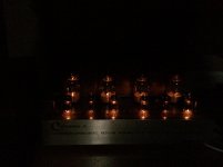
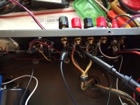
Nice lights out pic Cbox!
Kind regards,
Steve
I'm with Cbox in that it's a bit over my head, but I'll study the schematic you posted and see if it clicks. Thank you for the tips!
Nice lights out pic Cbox!
Kind regards,
Steve
Last edited:
lights out evidence
I agree, nice pic. Fun to stare at the amp when you're listening in the dark, right? This photo also shows one result of the filament voltage dropping resistors, R72 & R73, on V1 & V4: they're not as bright as the others!
I agree, nice pic. Fun to stare at the amp when you're listening in the dark, right? This photo also shows one result of the filament voltage dropping resistors, R72 & R73, on V1 & V4: they're not as bright as the others!
Bill,
Thanks for the link to the screen printing page. I look forward to see your progress. I would love to be able to make some nice looking panels for my own Cit 2.
ym
Thanks for the link to the screen printing page. I look forward to see your progress. I would love to be able to make some nice looking panels for my own Cit 2.
ym
You're welcome!
no prob, YM. My progress will be a little slow due to other duties, but it will be worked on a little bit each day.
Bill
no prob, YM. My progress will be a little slow due to other duties, but it will be worked on a little bit each day.
Bill
I can't seem to stop starring at it! LOL
WC> The filament resistors, and V1/V4 heater burning cooler - Is that a bad thing?
WC> The filament resistors, and V1/V4 heater burning cooler - Is that a bad thing?
Sorry for the over your head thing.
The issue is static and dynamic characteristics of the tube. The AC Balanced control is supposed to be set such that you have symmetrical outputs from the driver tube.
The problem is that the cathode coupling is where 1/2 of the driver tube gets its drive. If you look at my schematic or the original you will see the cathodes tied together. The problem is that this does not result in equal drive due to the mu of the tube. In a triode, the mu is a little lower so if the plate resistors are the same value, the AC waveforms will not both have the same amplitude. Pentodes have a lot more gain so having different plate loads is hardly worthwhile.
So if you have a triode driver tube you have to compensate for the lower mu by increasing the plate load resistance on the right-hand tube section (the one that has its grid at virtual ground) and there is a formula for that, but the problem here is that not all tubes are the same.
So the amp is equipped with an AC balance control to allow for exact adjustment (some amps, like the Marshall guitar amps, simply have the two plate load resistors slightly different according to the formula because they don't want the adjustment and are less concerned about distortion).
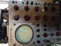
To adjust the AC balance, the best way is to use a sine wave generator and an oscilloscope. You can then adjust one of 2 ways: set the control so that the outputs from the driver are exactly symmetrical, or set it so the output of the amp is as low distortion as possible (this might involve running the amp at or near clipping). This is the 'dynamic' method of adjustment.
If you don't have those instruments, then you use a voltmeter to get the plate voltages on both halves of the driver to be the same voltage. This is the static method and is less accurate, as the static and dynamic characteristics of a tube can be different.
I hope this explains it...
The issue is static and dynamic characteristics of the tube. The AC Balanced control is supposed to be set such that you have symmetrical outputs from the driver tube.
The problem is that the cathode coupling is where 1/2 of the driver tube gets its drive. If you look at my schematic or the original you will see the cathodes tied together. The problem is that this does not result in equal drive due to the mu of the tube. In a triode, the mu is a little lower so if the plate resistors are the same value, the AC waveforms will not both have the same amplitude. Pentodes have a lot more gain so having different plate loads is hardly worthwhile.
So if you have a triode driver tube you have to compensate for the lower mu by increasing the plate load resistance on the right-hand tube section (the one that has its grid at virtual ground) and there is a formula for that, but the problem here is that not all tubes are the same.
So the amp is equipped with an AC balance control to allow for exact adjustment (some amps, like the Marshall guitar amps, simply have the two plate load resistors slightly different according to the formula because they don't want the adjustment and are less concerned about distortion).
To adjust the AC balance, the best way is to use a sine wave generator and an oscilloscope. You can then adjust one of 2 ways: set the control so that the outputs from the driver are exactly symmetrical, or set it so the output of the amp is as low distortion as possible (this might involve running the amp at or near clipping). This is the 'dynamic' method of adjustment.
If you don't have those instruments, then you use a voltmeter to get the plate voltages on both halves of the driver to be the same voltage. This is the static method and is less accurate, as the static and dynamic characteristics of a tube can be different.
I hope this explains it...
Last edited:
I actually do have an oscilloscope (an OLD tube Techtronix one, that hasn't been calibrated in about 30 years). I'm not the most skilled at using it however. I also have an HP 200CD oscillator (not working, think it needs recapped). Will that work? I have some Arduino's laying around too, function generator code is pretty easy to find. If you can help me with some step by step I'd love to document it for the other Deuce owners out there.
Last edited:
All you do is run the amp with a sine wave input.
The AC balance control is then adjusted for the purest sine wave output; sometimes this is best seen near full output depending on the tubes.
A distortion analyzer works best, but a scope will do 🙂
The AC balance control is then adjusted for the purest sine wave output; sometimes this is best seen near full output depending on the tubes.
A distortion analyzer works best, but a scope will do 🙂
ok I have 6550 welded plates, I think GE (they came with the amp originally and thats the closest resemblance I can find). I looked up on youtube how to read the sine wave output when doing AC balance - looks pretty cut and dry. (as clean of a sine wave as I can get it) Question though, where do I hook up the scope and how much voltage should I expect at those points? (so I don't kill my scope) Should I have the resistor across the speaker terminals as well?
Sorry to keep bugging you, and thank you for being so helpful
Sorry to keep bugging you, and thank you for being so helpful
Put the scope on the speaker terminals.
It is helpful to have a non-inductive dummy load that can handle the power, to load the OPT and tubes properly. Maybe I should restate that. Its good practice to prevent damage to use a dummy load. The non-inductive part is to prevent errors in the AC output voltage reading.
The scope won't have any troubles handling the voltage. Since the amp makes 60 watts into 8 ohms, the peak to peak voltage should be about 62 volts.
Alternatively, put the scope on the plate connections of the driver tube sections. I like to do the output of the amp since that reading has you compensating for dynamic mismatch between the power tubes. If your power tubes really are matched though then there will be little difference between the methods.
they are 52 years old and I doubt Harman supplied matched tubes. Think I'll try it at the plates instead. Might be a few days I got homework to conquer first.
Ok so here is how my AC balance nightmare went...
I first wanted to try the multimeter bias... just to see if everything would balance out. I made meter leads with .01uF caps and everything. I replaced the bias resistors at the pot down to 4.7 like Jim recommends on his site and put a fresh 330R on the meter.
NOTE TO EVERYONE: DO NOT FOLLOW THE SCHEMATICS FROM HARMAN KARDON'S WEBSITE! THEY ARE WRONG! THE AMP WILL WORK BUT NOT DESIRABLY! THE BIAS WILL BE TOO HOT AND THE POTS WILL MAKE LITTLE EFFECT! FOLLOW THE SCHEMATICS FROM JIM MCSHANE'S SITE UNLESS HE TELLS YOU OTHERWISE!
I ordered a bunch of odd resistors for NOTHING!
Now that my rant is over...
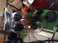
I made some dummy loads out of some large light bulbs. Cold they read 2R so I went to the 4R tap with them. I re-biased the tubes at 1.5v within +/-.05 volts for the 20R resistors. Then I started to tackle the AC balance. cap-leads ready, hooked up to pin 8 on Channel A - then plugged in the signal line. Light bulb starts to light up, 6 volts AC!!!!! Pot makes about 1 volt difference! So I shut down, and replaced all the 10K resistors on pin 5 of the output tubes. One was at 13.5K so that was pretty out of range. Repeat process... 4v. Move to B channel, 6.09 is as close as I can get, pot turned full one way.
What else should I be checking here?
I first wanted to try the multimeter bias... just to see if everything would balance out. I made meter leads with .01uF caps and everything. I replaced the bias resistors at the pot down to 4.7 like Jim recommends on his site and put a fresh 330R on the meter.
NOTE TO EVERYONE: DO NOT FOLLOW THE SCHEMATICS FROM HARMAN KARDON'S WEBSITE! THEY ARE WRONG! THE AMP WILL WORK BUT NOT DESIRABLY! THE BIAS WILL BE TOO HOT AND THE POTS WILL MAKE LITTLE EFFECT! FOLLOW THE SCHEMATICS FROM JIM MCSHANE'S SITE UNLESS HE TELLS YOU OTHERWISE!
I ordered a bunch of odd resistors for NOTHING!
Now that my rant is over...
I made some dummy loads out of some large light bulbs. Cold they read 2R so I went to the 4R tap with them. I re-biased the tubes at 1.5v within +/-.05 volts for the 20R resistors. Then I started to tackle the AC balance. cap-leads ready, hooked up to pin 8 on Channel A - then plugged in the signal line. Light bulb starts to light up, 6 volts AC!!!!! Pot makes about 1 volt difference! So I shut down, and replaced all the 10K resistors on pin 5 of the output tubes. One was at 13.5K so that was pretty out of range. Repeat process... 4v. Move to B channel, 6.09 is as close as I can get, pot turned full one way.
What else should I be checking here?
If it were me,I would use the procedure from the manual (using the internal meter)as a starting point.
That sounds like a open cathode resistor, or an overloaded tube,
Do all of the bias positions work /adjust on the meter?
Do all of the bias positions work /adjust on the meter?
The Bias positions all work properly... the Bias mark = ~1.2-1.4v
Cathode resistors are all brand new
Cathode resistors are all brand new
The meter does show balance with no signal, or just barely off.
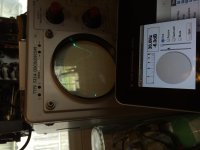
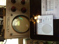
So just on a whim, I thought I'd try a different method of getting a sine wave, and used the sound card in my computer. Volume up full, I ran 20, 60, and 100hz through the amp and checked the sine wave from the output transformer... They look perfect on my scope.
So just on a whim, I thought I'd try a different method of getting a sine wave, and used the sound card in my computer. Volume up full, I ran 20, 60, and 100hz through the amp and checked the sine wave from the output transformer... They look perfect on my scope.
Attachments
- Home
- Amplifiers
- Tubes / Valves
- Harman Kardon Citation II - rebuild questions