BTW Jim, I wanted to ask. Why did you chose to use the dual section caps in your PS upgrade kits? Dual section caps are probably the worst bargain of the century (least capacitance for your $) Using 140uF 450V caps on V1/V4 at the turret board, there's now 2 free spots on my cap rail and these things cost mere dollars (rather than $20+ apiece)
BTW Jim, I wanted to ask. Why did you chose to use the dual section caps in your PS upgrade kits? Dual section caps are probably the worst bargain of the century (least capacitance for your $) Using 140uF 450V caps on V1/V4 at the turret board, there's now 2 free spots on my cap rail and these things cost mere dollars (rather than $20+ apiece)
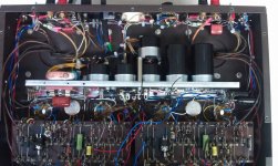
There's no room for anything else! And keep in mind that using them allows us to increase the V1/V4 decoupling capacitance from 50 uf per channel to 150 or 200 uf per channel. I don't want electrolytic caps on the turret boards - a) they take up room I use for other things, and b) it's the hottest place in the amp, not where I want to put the electros for long life.
You can shoehorn more Panasonic caps on the PS bracket using another cap stack like we use, but I like to leave SOME open space for air to circulate in there. And it gets really hard to work on with those dual sections replaced with a stack of Panasonics.
Also, with today's higher line voltages I consider 450 volt caps to be marginal. 500 volts minimum is what we use, which is another reason why the duals work well.
BTW, the amp pictured went to Phil Palombi, a Grammy winning jazz bassist from the trio Tri-Fi (look 'em up, they're GREAT - www.tri-fi.com) with incredible ears - he says it's the best amp he's ever heard. So we must be doing something right!
Attachments
Thanks for the reminder about how hot the turret boards get... still, 2 140uF could easily be moved to a terminal strip on the capacitor rail. I already have the caps on hand so I'm gonna try it out and see how it goes.
Looks frickin beautiful BTW... your work is always top-notch
Looks frickin beautiful BTW... your work is always top-notch
Jim,BTW, the amp pictured went to Phil Palombi, a Grammy winning jazz bassist from the trio Tri-Fi (look 'em up, they're GREAT - www.tri-fi.com) with incredible ears - he says it's the best amp he's ever heard. So we must be doing something right!
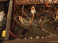
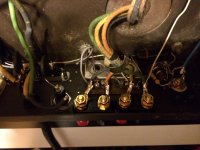
That amp has a number of mods to it that I don't recognize. Have you talked about them on your website? Things like the extra transformer on the cap bracket, the semiconductor device on the turret board, the extra trim pots on the turret board, etc.
Please tell us more.
Thanks,
---Gary
Gary,
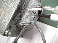
The little toroid deals with THE weak spot in the power trafo of the "Deuce", which is the bias winding. "Deuce" bias windings tend to go bad. 🙁 Jim McShane and Don Sachs are dealing with the problem, before it occurs.
I have a strong hunch that the TO220 case parts on the turret boards are 10M45S CCSes and the pots. are the adjustments.
Gary,
The little toroid deals with THE weak spot in the power trafo of the "Deuce", which is the bias winding. "Deuce" bias windings tend to go bad. 🙁 Jim McShane and Don Sachs are dealing with the problem, before it occurs.
Correct. There is a solder joint in the bias winding (see the pic attached) and after 50 years it has work hardened and sometimes fails or goes intermittent. That was the cause of a number of KT-88 failures (that of course got blamed on the tubes, which was NOT the case) as you can imagine. The trafo could be rewound but that is VERY expensive - or you can do as we did and design a bias raw supply that feeds right into either the stock bias circuit or our upgraded one. We put together a kit for that and we recommend EVERY Cit II get the kit unless the trafo has been rewound.
I have a strong hunch that the TO220 case parts on the turret boards are 10M45S CCSes and the pots. are the adjustments.
Again Eli is correct. Those are CCS parts.
I'm headed out the door and I'll be away all week so I may not be able to respond to any new posts on this.
Attachments
Last edited:
Well while I'm waiting for parts, I wanted to ask some questions about cosmetics. The bottom panel is covered in cigarette tar (almost a gold color) and the brown paint on the amp is in pretty bad shape. There's also a rust spot spot on one of the edges about 1" around. I REALLY don't want to lose all the screen printing or destroy the originality value of it. Is it really tough to get screen printing redone on a chassis like this? Is it a horrible thing to paint it a new color? (I'm more attracted to black audio equipment)
Thanks
Thanks
IME, the best combination is RCA in the voltage amplifier positions and GE JAN in the phase splitter positions. RCA for "tone" and GE JAN for toughness. Certainly, all RCA will work.
BTW, close matching is not essential.
BTW, close matching is not essential.
I got them for a very good price (better than buying 6 NOS unmatched any brand) so I won't complain, but I'll keep an eye out for a couple of the GE JAN going at a good price. Right now I'm a bit more pressed for new 6550's and a quad set of 12AX7's for my Fisher 400C. I have been hearing RAVE things about Mullard reissue tubes, and right now those are the ones I desire. Like I said I didn't grow up in tubes so I don't necessarily want it to sound "old" just REALLY good.
Is making a thread about the rebuild experience encouraged on this forum? I'm sure Jim could make a rebuild thread would be the go-to end-all but since I've got these things torn apart I'd hate to not take the opportunity to take pictures and share methods. If anybody is interested in seeing the pictures of this thing torn apart I'll keep taking and posting but if not I'll just dial it back to asking questions when I hit a wall.
Is making a thread about the rebuild experience encouraged on this forum? I'm sure Jim could make a rebuild thread would be the go-to end-all but since I've got these things torn apart I'd hate to not take the opportunity to take pictures and share methods. If anybody is interested in seeing the pictures of this thing torn apart I'll keep taking and posting but if not I'll just dial it back to asking questions when I hit a wall.
I would just post the rebuild to this thread, if you wish I can change the thread title to reflect.
I have like 30 things on order from Ebay, and I got NO mail today. It was like waking up thinking it was christmas, and its still just christmas eve.
So just a little update:
Still waiting for parts to arrive. In the meantime, Mr. JIM MCSHANE, I put a NEW fuse holder in and put a switch in the convenience outlet AS YOU ORDERED! 🙂D jk) If only I could've found this switch 2mm wider it would have been perfect but not a bad fit as is and is good to 10 amps constant. I'm not a fan of slide switches.
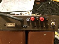
After fidgeting with the RCA's for a while, I decided I'm putting both input connections on the right side (where there are 2 jacks) and putting the test signal AC jack on the other side by itself. Just personal preference... I'm bad about plugging things in blind (don't want to imagine what that AC signal might do to my iPod) and makes for neater connections IMO. I'm replacing the signal wires with a miniature RG-59U that I used to use to install projectors. Was awesome stuff - very flexible and thin so it doesn't break the solder joints on the projector's RCAs back when HDMI/DVI were uncommon. Could carry an analog 1920x1080 progressive picture for over 50 feet hanging around electrical wires without any noticeable interference so it should be more than plenty for the deuce.
The 1.8K Bias resistor had wandered all the way to 3.8K! Over double value!
I got the front panel cleaned up fairly well. There is a small bit of corrosion on the S in Stereophonic that I can't get off, and I already did a tiny bit of damage to that S with Brasso. Barely noticeable, leaving it alone for now.
BTW I have picked and combed thru this thing really well. It really looks like it was barely used. The circuit board is just BARELY discolored under the large power resistors, and all the wires are just dusty. They all have very good coloration and the insulation looks and feels practically new with good flexibility/no cracking. Thinking for now I'm going to leave most of the existing wiring in place, and plan to do a major overhaul after college. That will give some time to see how Carver's KT120 mods work out, learn more about tubes and amps themselves, and save that decision for a later date when I'm more knowledgable about what I'm doing.
Still waiting for parts to arrive. In the meantime, Mr. JIM MCSHANE, I put a NEW fuse holder in and put a switch in the convenience outlet AS YOU ORDERED! 🙂D jk) If only I could've found this switch 2mm wider it would have been perfect but not a bad fit as is and is good to 10 amps constant. I'm not a fan of slide switches.
After fidgeting with the RCA's for a while, I decided I'm putting both input connections on the right side (where there are 2 jacks) and putting the test signal AC jack on the other side by itself. Just personal preference... I'm bad about plugging things in blind (don't want to imagine what that AC signal might do to my iPod) and makes for neater connections IMO. I'm replacing the signal wires with a miniature RG-59U that I used to use to install projectors. Was awesome stuff - very flexible and thin so it doesn't break the solder joints on the projector's RCAs back when HDMI/DVI were uncommon. Could carry an analog 1920x1080 progressive picture for over 50 feet hanging around electrical wires without any noticeable interference so it should be more than plenty for the deuce.
The 1.8K Bias resistor had wandered all the way to 3.8K! Over double value!
I got the front panel cleaned up fairly well. There is a small bit of corrosion on the S in Stereophonic that I can't get off, and I already did a tiny bit of damage to that S with Brasso. Barely noticeable, leaving it alone for now.
BTW I have picked and combed thru this thing really well. It really looks like it was barely used. The circuit board is just BARELY discolored under the large power resistors, and all the wires are just dusty. They all have very good coloration and the insulation looks and feels practically new with good flexibility/no cracking. Thinking for now I'm going to leave most of the existing wiring in place, and plan to do a major overhaul after college. That will give some time to see how Carver's KT120 mods work out, learn more about tubes and amps themselves, and save that decision for a later date when I'm more knowledgable about what I'm doing.
Attachments
I have like 30 things on order from Ebay, and I got NO mail today. It was like waking up thinking it was christmas, and its still just christmas eve.
Hmmm, Who'd you get the RCAs from, do they have more?
they look prety good if they have more
I'll buy some for my citation.
What were the othr orders.
YOU know you can always orderfrom someone else
and dwhen originals straggles come, you can refruse
the and they automatically back and ou get yor money back., no problem.
What parts are you waiting on that is it bein late at?
Yeah I know there is nothing worse then ready to finishe...but
you have to wait
Wait
Wait Wait Wait Wait
Wait
Wait
Wait waiting is not so nice w'll have to see.
Breal a legs on loyou problems.
let me know what ou want to do...
Sync
I've expended the last of my energies for the night. Put gold lugs on the OP xfrmr leads for a good solid connection to the terminals, and redid all of the 120v circuit work. Also took an old slide switch apart and used it for a switch bracket. Now the rocker switch feels like it is MEANT to be there!
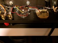
I thought I remembered Jim saying there was no room for the thermistors before the transformer?
Who says you can't polish a turd? 😀
I thought I remembered Jim saying there was no room for the thermistors before the transformer?
Who says you can't polish a turd? 😀
Attachments

Got the caps in (FINALLY!) but I have to commend the seller. I think he thought I was upset about it, he refunded me my money and sent me 4 (instead of 2).
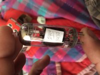
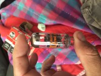
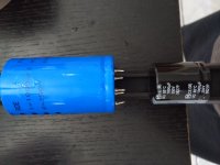
What I can't believe is the difference between the brands. The black capacitor is Panasonic brand, and the blue is the Roe. The Roe is rated to 15K hrs @ 105*C, the Panasonic at 2K hrs @ 85*C. (See the pics attached) The panasonic caps cost about $3 more than the Roe for 2.
The Roe capacitors have 5 connections, only 2 of them hook up to anything... but I did have to open up the hole a little for the capacitor to fit, and drill holes for the cap clamps.
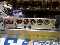
So last night I spent time reconnecting the "Business end" of the deuce. Hooked up all the Bias pots, selector, meter, speaker terminals, etc. I have a feeling that I need to take out that white feedback loop wire and replace it, its a bit short. (the one hooked up to the green wire on the output transformer)
Wanted to ask the experts (esp Mr. Jim McShane) if there are any "universally agreed upon" schematics for the deuce. HK has the most complete documentation I've found on their site, and there are several suggested resistor changes on their schematics. I have some additional resistors on my original schematics (surge protection around the doubler diodes), and Jim I'm sure has chosen a few resistors to change for the better as well.
Also, why a 1400V cap on the doubler? There's only 465v (without load) isn't it? Wouldn't a 600V do fine there?
Any help is greatly appreciated
What I can't believe is the difference between the brands. The black capacitor is Panasonic brand, and the blue is the Roe. The Roe is rated to 15K hrs @ 105*C, the Panasonic at 2K hrs @ 85*C. (See the pics attached) The panasonic caps cost about $3 more than the Roe for 2.
The Roe capacitors have 5 connections, only 2 of them hook up to anything... but I did have to open up the hole a little for the capacitor to fit, and drill holes for the cap clamps.
So last night I spent time reconnecting the "Business end" of the deuce. Hooked up all the Bias pots, selector, meter, speaker terminals, etc. I have a feeling that I need to take out that white feedback loop wire and replace it, its a bit short. (the one hooked up to the green wire on the output transformer)
Wanted to ask the experts (esp Mr. Jim McShane) if there are any "universally agreed upon" schematics for the deuce. HK has the most complete documentation I've found on their site, and there are several suggested resistor changes on their schematics. I have some additional resistors on my original schematics (surge protection around the doubler diodes), and Jim I'm sure has chosen a few resistors to change for the better as well.
Also, why a 1400V cap on the doubler? There's only 465v (without load) isn't it? Wouldn't a 600V do fine there?
Any help is greatly appreciated
Attachments

Last edited:
I thought I remembered Jim saying there was no room for the thermistors before the transformer?
Nope, never said that. I use inrush limiters almost all the time, but I use them differently than you do.
Also, where is the 39 Ohm resistor/.039 uf cap newtwork from the 16 Ohm terminal to ground? That network is very important.
Finally, just so no one is confused that AC power switch you used is not the switch I recommend.
Last edited:
What I can't believe is the difference between the brands. The black capacitor is Panasonic brand, and the blue is the Roe. The Roe is rated to 15K hrs @ 105*C, the Panasonic at 2K hrs @ 85*C. (See the pics attached) The panasonic caps cost about $3 more than the Roe for 2.
You are comparing apples and oranges - the ROE spec is for "useful life" and at 85 C - which is far more lenient than the Panasonic "endurance" spec is. The Panasonic TS-ED endurance is spec'd at 105 C and at maximum rated ripple current - which is 2.84 amps at 120 Hz and 4.06 amps at 10K Hz.
Now the Panasonic I'm referring to is the TS-ED series, which is my favorite electrolytic cap. You may have opted for a different series, but in any case you can't directly compare the ratings since they are not rated under identical conditions.
Wanted to ask the experts (esp Mr. Jim McShane) if there are any "universally agreed upon" schematics for the deuce. HK has the most complete documentation I've found on their site, and there are several suggested resistor changes on their schematics. I have some additional resistors on my original schematics (surge protection around the doubler diodes), and Jim I'm sure has chosen a few resistors to change for the better as well.
The factory schematic is what I go by, you can see/download it on the Resources page on my site. Other than the power supply and one bias resistor per channel and the cathode resistors on the power tubes I don't change any resistors except for the very small changes (like from 270 to 274 Ohms) required to use modern resistors.
The surge protection around the diodes is not needed with modern diodes. The old top hats were nowhere near as durable and the 1 meg carbon comps they added were attempts to save those expensive diodes (back then they were very pricey!). A modern fast/soft recovery diode like I use in my kits has 6 times the current ratings of the old top hats at the same voltage rating - for 10% of the cost.
The other resistor change was to the value of the meter calibration resistor so that when the meter was on the bias mark the tube was passing 90 ma instead of 100 ma. Even the tubes of the day couldn't take the pounding!
Also, why a 1400V cap on the doubler? There's only 465v (without load) isn't it? Wouldn't a 600V do fine there?
No! In fact I use a 1600 volt snubber rated cap. There is all kinds of stuff riding on the DC voltage at that point. Put a scope on it and take a look. Then you'll see why I want a very stout cap in that spot. 600 volts is not adequate.
It's your amp, so you can build it any way you want. But I have 30+ years of experience with these and have built or supplied parts/kits to rebuild 100s of them. So I'm trying to be helpful - even if what I say doesn't agree with your thoughts. There is no offense intended whatsoever!!
Correct, Jim did not advise me to use that style/brand/part# of switch, only implied that I simply put a switch in the place of the convenience outlet. However, it is a nice fit for that location. You can find them on e-switch.com and they do offer samples if you just want to try one out.
You very much do suggest the use of the inrush limiters as well, I just remember seeing another post somewhere - another person asked why you didn't use the thermistors before the transformer primaries rather than on the HV secondary, if I recall your response was that there was no room for them. In my build, I have allocated the room for them, so I wanted to share that with you. I'm not knowledgable enough to say your method or on the primaries is better (I've scoured the forum on both), but if it is better and it helps you (or anyone on this forum) - it kind of helps the common good as well. I'm not taking all these pictures for bragging rights. All of the people who have stripped these things to their bare chassis, or replaced a few common components and TOLD THE STORY ABOUT IT have helped me learn what I need to do and I feel that I should contribute something back, for the next person who finds one of these in their grandparents garage. Will it spark their interest, or will it turn into a quick $ on ebay? Jim, you're the inspiration of why I got this thing running in the first place rather than pawning it off for some "Go fast" goodies for my car. Your passion for the amp, all its "defects" (as some called it in another posts), and how it just works made me want to know what I was about to give up. Even though I've only listened to it for a total for 5 hours (20 minutes at a time), I've struggled through 10 years of moving through multiple states and struggling paycheck to paycheck and I have refused to part with it. I'm sorry I can't say thank you by ordering every part you suggest for it, or just sending it to you for your treatment. With all the havoc I have gone through and held onto that amp for, it's a staple in my life at this point and I want to know what makes it tick. I'm sure your kits all fit into the "turd" (loving nickname) like fine cut puzzle pieces and with absolute finesse, but it would take away the experience that I need from it. If I ever know anyone with a Citation anything ever again in my life, your name will be the first I mention I assure you. I hope you don't take offense when I "question" your methods, its all part of just wanting to understand and I try to do it light heartedly. I tend to forget that keyboards aren't good comedians.
That RC network is MOST DEFINITELY in there, I assure you. The cap end is crimped into the gold lug, running to a terminal strip where the resistor is mounted. I was trying to do some minor cosmetic clean up while I'm in there. I did a test fit with the new cap board, and I have quite a bit of room freed up! I'm waiting for an order of resistors to come in before I mount it in (should be Monday) but I'll take some pics of it.
Correct, Jim did not advise me to use that style/brand/part# of switch, only implied that I simply put a switch in the place of the convenience outlet. However, it is a nice fit for that location. You can find them on e-switch.com and they do offer samples if you just want to try one out.
You very much do suggest the use of the inrush limiters as well, I just remember seeing another post somewhere - another person asked why you didn't use the thermistors before the transformer primaries rather than on the HV secondary, if I recall your response was that there was no room for them. In my build, I have allocated the room for them, so I wanted to share that with you. I'm not knowledgable enough to say your method or on the primaries is better (I've scoured the forum on both), but if it is better and it helps you (or anyone on this forum) - it kind of helps the common good as well. I'm not taking all these pictures for bragging rights. All of the people who have stripped these things to their bare chassis, or replaced a few common components and TOLD THE STORY ABOUT IT have helped me learn what I need to do and I feel that I should contribute something back, for the next person who finds one of these in their grandparents garage. Will it spark their interest, or will it turn into a quick $ on ebay? Jim, you're the inspiration of why I got this thing running in the first place rather than pawning it off for some "Go fast" goodies for my car. Your passion for the amp, all its "defects" (as some called it in another posts), and how it just works made me want to know what I was about to give up. Even though I've only listened to it for a total for 5 hours (20 minutes at a time), I've struggled through 10 years of moving through multiple states and struggling paycheck to paycheck and I have refused to part with it. I'm sorry I can't say thank you by ordering every part you suggest for it, or just sending it to you for your treatment. With all the havoc I have gone through and held onto that amp for, it's a staple in my life at this point and I want to know what makes it tick. I'm sure your kits all fit into the "turd" (loving nickname) like fine cut puzzle pieces and with absolute finesse, but it would take away the experience that I need from it. If I ever know anyone with a Citation anything ever again in my life, your name will be the first I mention I assure you. I hope you don't take offense when I "question" your methods, its all part of just wanting to understand and I try to do it light heartedly. I tend to forget that keyboards aren't good comedians.
That RC network is MOST DEFINITELY in there, I assure you. The cap end is crimped into the gold lug, running to a terminal strip where the resistor is mounted. I was trying to do some minor cosmetic clean up while I'm in there. I did a test fit with the new cap board, and I have quite a bit of room freed up! I'm waiting for an order of resistors to come in before I mount it in (should be Monday) but I'll take some pics of it.
No offense taken on my end!! Don't give it a thought.
And I'm glad to hear the output network didn't get left out.
I use the inrush limiters on the B+ supply because I don't want to do anything to slow down the rise of the bias voltage even just a little - which is what happens when they are in the primary. Maybe I'm a bit over the top on this - but that's okay by me. Physically you can see the limiters at the left end of the power supply bracket in the pic I attached.
Attachments
- Home
- Amplifiers
- Tubes / Valves
- Harman Kardon Citation II - rebuild questions