OK so today I finally took some time to finish up. The cap board is in, everything is mounted. I had completely forgotten that I had cut the bias winding wires very close to the transformer back when I went around with it the first time, so I had to extend those wires. Replaced the white wires for the feedback loops, one of them had a bad solder joint and was sitting loose on the post so glad I did!
So went to fire it up for the first time. No clang, perfectly silent startup. Now the 6550 tubes are starting to glow orange shortly after startup 🙁 I tried to adjust the bias but it goes off the meter.
I have changed R76 to 22ohm per factory schematics. I did however put in the 20ohm resistors that Jim recommends to use on his site (for KT88's but still).
My brain is kind of fried for the night, but I really don't wanna stop. Any ideas?
Bias transformer winding puts out 53v to ground from one of the wires to ground (don't have the color codes, wires blackened by the xfrmr), and the other about 10v to ground and then about 10v lead to lead. I changed out both caps as well, 450v 33uF because I have a few of them on hand.
So now I'm trying to use the extra bias transformer I have. It's putting out 86v ac and capable of around 200ma. The Bias supply is drawing 150-160ma (secondary) no matter where I position the bias pots and the tubes are starting to glow orange shortly after turn on.
So now I'm trying to use the extra bias transformer I have. It's putting out 86v ac and capable of around 200ma. The Bias supply is drawing 150-160ma (secondary) no matter where I position the bias pots and the tubes are starting to glow orange shortly after turn on.
Are you sure you don't have the bias filter caps in backwards?? That is a lot of current! If the caps were in backwards they would draw a lot of current- and kill the bias voltage- pretty much a dead ringer for your complaint.
I'm hooking up according to the schematics. The stripe side (negative) for both caps are connected together in the center, and to the back side of the diode (stripe towards transformer). The positive side of one goes to the 820ohm resistor, which connects to the positive side of the other, which connects to ground. I have tried it with a 1.8K like the orig schematics, and the 820K which is HK's website schematics. The picture is of the 1.8K I had to series 2 resistors to get the value.
Attachments
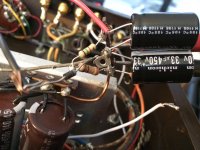
Nevermind I got it. I had the diode backwards *BLAH!*
Listening direct with my iPod right now, and drooling!!!!! OMG!!!! LIKE WARM BUTTER AND HONEY BEING POURED INTO MY EARS!!!!!!!!!!!!!!!!!!!!!!!!!!!!!!!!!!!!!!!!!
anybody have a suggestion of whether to use the 820R or the 1.8K resistor in the bias circuit tho?
Listening direct with my iPod right now, and drooling!!!!! OMG!!!! LIKE WARM BUTTER AND HONEY BEING POURED INTO MY EARS!!!!!!!!!!!!!!!!!!!!!!!!!!!!!!!!!!!!!!!!!
anybody have a suggestion of whether to use the 820R or the 1.8K resistor in the bias circuit tho?
Last edited:
Cbox, glad it's working! Nice job. Congrats!!!! 🙂
Atmasphere, referring back to the schematic you posted as well as your comments, would you be willing to update it with the changes you mentioned?
Unfortunately, I don't know circuit design but am able to build. I would love to try what you mentioned but don't know how to get there. Hence I figured it couldn't hurt to ask.
Thanks,
Steve
Atmasphere, referring back to the schematic you posted as well as your comments, would you be willing to update it with the changes you mentioned?
As you can see there are not 3 feedback loops but one. While the amp sounds fine, these days I question the amount of feedback (6 db), as lower amounts of feedback can be risky in some designs. Since the triodes are so much more linear it did not seem to be helpful to run feedback around them, especially since this circuit has less gain overall.
If I were to do this again, I would readjust the plate values of the driver section as it clearly is doing no good to have them be equal due to the cathode coupling/mu issue. I would also consider a 2-stage CCS for the circuit.
Unfortunately, I don't know circuit design but am able to build. I would love to try what you mentioned but don't know how to get there. Hence I figured it couldn't hurt to ask.
Thanks,
Steve
Last edited:
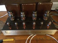
Here's a picture of the finished product. I'm using an old Pioneer receiver as a preamp right now, the Fisher 400-C isn't cooperating. I replaced the triple 30uF cap and it still has a darned hum and its distorted. Sounds amazing though, none of the digital amps I've had can run the electrostats like the HK can. The spatial imaging is astounding! I was in my bathroom and thought I heard Trent Resnor (sp?) singing in the living room.
BTW does anybody know who made the original 12BY7's? (The HK branded ones) I was hoping they would be GE because of the earlier discussion about the GE's working really well in the phase splitter position.
I do REALLY need one last bit of help with a couple final issues. First off, I wanted to see if someone could tell me how to find out how much Bias current is actually running through the tube with a multimeter (Hopefully without desoldering anything).
I also need help with the Bias circuit as well. The stand alone transformer I am using for Bias is putting out 86v AC. I know this has raised the bias circuit's voltage. E=I/R so if I've raised the voltage I've probably raised the current as well. The Bias meter at max setting will only go about 80% of the bias mark (between the AC bal and bias hashes). Is this something I need to worry about? The tubes seem to be running cool, I've been running it for hours and they haven't started to glow at all. Jim, if you're still reading, I'm hoping and praying you can tell me exactly where to put a couple resistors and be done with it if this is a problem.
was asking earlier how to set ac balance with a multimeter, once again, thanks Jim! ur site is awesome!
Attachments
Last edited:
Hi Bill,
I would also like a copy of the pdf's as well.
Thanks,
Scott
I would also like a copy of the pdf's as well.
Thanks,
Scott
Hi all
I'm also in the process of rebuilding a Citation II from the ground up. I did go to Jim McShane for the rebuild kits since his parts are well proven and his prices are really good.
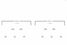
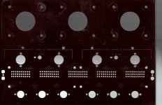
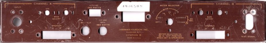
But my post concerns the process of making it look as good as it will sound. My chassis is also pretty beat up. The aluminum needs some straightening, as does the steel in a couple spots, and the lettering is really tough to even see, let alone read. I decided to try repainting the chassis and transformers myself, then screen printing the lettering on using gold metallic printing ink. I went to a local (Mesa, AZ) auto paint store and bought some base coat and clear coat. I also got some equipment and chemicals to do the printing as well. I have already scanned the chassis parts to get a full size image, and then processed them with GIMP freeware to get correct sized templates. (BTW, if anyone want the pdfs let me know and I'll post them. As I progress I would be happy to post some pics. I won't be getting it to the painting until some time next week, so it will be awhile before pics come out.
Bill
Hi Bill,
I would appreciate a copy as well. Any chance of providing some details as to how to do the screen printing?
TIA
ym
I would appreciate a copy as well. Any chance of providing some details as to how to do the screen printing?
TIA
ym
Fisher 400-C is running OK, another complete recap job (but a MUCH easier one). Now I just need a turn table and I'll have a 100% analog setup.
pdf scans and templates
Here are the back and front panel pdfs. On my Epson B-size printer these print out full size. The top panel file is too big as a pdf, so I'll try attaching a different format in the next post.
As I progress I can attach photos here, or maybe start another thread just for that purpose.
Bill
Here are the back and front panel pdfs. On my Epson B-size printer these print out full size. The top panel file is too big as a pdf, so I'll try attaching a different format in the next post.
As I progress I can attach photos here, or maybe start another thread just for that purpose.
Bill
Attachments

screen printing How To
YM
I'd be happy to document how I do it, but you realize I'm a novice. 🙂 I did find a website that walked through the process for a radio front panel, and my methodology will follow his. Screen Printing Radio Panel
I got some good starting advice and some supplies from a local screen printing supply house. They mostly supply t-shirt printers, but they had a couple people who know the specifics of printing on metal chassis and the like. They had the correct emulsions and inks as well as the finer mesh screens in stock. I'll be practicing on some scrap panels first so I can also document pitfalls as I learn them. Should be fun, I'm looking forward to the experience. I've always liked brand new looking stuff. Looking at old beat up and tired HiFi gear makes me feel old beat up and tired. Which I am, but certainly don't need any reminders...
Hi Bill,
I would appreciate a copy as well. Any chance of providing some details as to how to do the screen printing?
TIA
ym
YM
I'd be happy to document how I do it, but you realize I'm a novice. 🙂 I did find a website that walked through the process for a radio front panel, and my methodology will follow his. Screen Printing Radio Panel
I got some good starting advice and some supplies from a local screen printing supply house. They mostly supply t-shirt printers, but they had a couple people who know the specifics of printing on metal chassis and the like. They had the correct emulsions and inks as well as the finer mesh screens in stock. I'll be practicing on some scrap panels first so I can also document pitfalls as I learn them. Should be fun, I'm looking forward to the experience. I've always liked brand new looking stuff. Looking at old beat up and tired HiFi gear makes me feel old beat up and tired. Which I am, but certainly don't need any reminders...
- Home
- Amplifiers
- Tubes / Valves
- Harman Kardon Citation II - rebuild questions