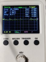
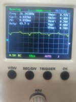
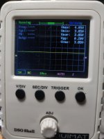
All four outputs removed. This is what I see on the gate legs of Q207 and Q208 in the first pic, and Q209 + Q210 in the second pic.
Not sure if this is usable data from the DSO, or if using the OWON is a requirement to achieve usable data.
Not sure if this is usable data from the DSO, or if using the OWON is a requirement to achieve usable data.
Attachments

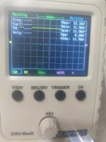
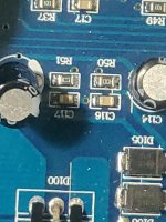
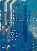
This is what is on the last two pins of the driver board. There really isn't anything else on any of the other pins when checked with a scope or multimeter... This is with the scope grounded to the - speaker terminal.
Attachments
I need the DC voltage on all pins of the header. Copy and paste the following list and fill in the blanks.
Pin 1:
Pin 2:
Pin 3:
Pin 4:
Pin 5:
Pin 6:
Pin 7:
Pin 8:
Pin 9:
Pin 10:
Pin 11:
Pin 1:
Pin 2:
Pin 3:
Pin 4:
Pin 5:
Pin 6:
Pin 7:
Pin 8:
Pin 9:
Pin 10:
Pin 11:

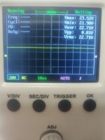
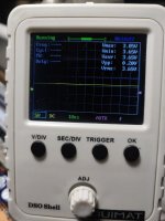
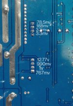
Some progress. I replaced the two 10ohm resistors and jumpered the speaker- terminal to the GND terminal and there are signs of life. The power up sequence with the LEDs occurs with the red protection lighting up for two seconds and then the green led illuminates. The new driver board voltages are posted below.
Attachments
Does it produce audio?
With nothing connected to the amp (not even the ground jumper), what's the resistance between the primary ground and the negative speaker terminals?
With nothing connected to the amp (not even the ground jumper), what's the resistance between the primary ground and the negative speaker terminals?
No audio as it goes into protection as it powers up with outputs installed. +rail voltage goes to the speaker terminal. Getting +rail voltage on the gates of the high side outputs.
With nothing connected to the Amp, there is 36k ohms between GND and Speaker - terminals.
With nothing connected to the Amp, there is 36k ohms between GND and Speaker - terminals.
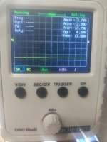
With no output FETs installed, what signal do you see on the two terminals that read 4.7 and 4.5v?
For the 17 and the 23mv pins, does either start near 12v when remote is initially applied and after a couple of seconds drop to very near 0v (as they are in the photo)?
Pin 4 with the +17.7mv sits at 12.7v without remote and all the way until the red protection LED turns green and then it drops to 17mv.
Pin 6 rests at 3mv without remote, when remote is applied, there is a slight jump in - voltage and then it drops back down to 23mv or so.
Pin 6 rests at 3mv without remote, when remote is applied, there is a slight jump in - voltage and then it drops back down to 23mv or so.
Pin 4 appears to be the mute pin. Pin 6, audio.
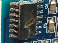
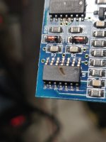
Do you see any signal on pin 1 or pin 7 of the 8-pin IC on the driver board?
Do you see any signal on pin 1 or pin 7 of the 8-pin IC on the driver board?
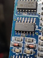
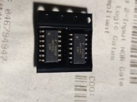
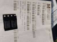
Discovered that the 74HC02 ICs are damaged when I went to check them. I have MM74HC02MX on hand, can I use them as replacements?
Attachments
- Home
- General Interest
- Car Audio
- Hardbass mono not turning on