I was having problems with my amp that had the old style driver boards without offset adjustment pot. So I purchased brand new stock blank driver boards (last version made) and stuffed with new parts. I can bias the amp OK, but the DC offset is 26-27 volts in both channels! Also, don't understand why my relay clicks on with all this offset. The DC offset adjustment pot does nothing when turned. Any idea where I should start looking?
Attachments
Pictures of the actual board top and bottom are very helpful.
Sounds like you either have a bad component, solder bridge or incorrectly installed transistor (wrong type or wrong way around).
Assume +/-main voltages are good?
Did you measure voltage on relay? Right before, to verify? Does seem odd it would activate if it’s a true speaker protection relay.
Sounds like you either have a bad component, solder bridge or incorrectly installed transistor (wrong type or wrong way around).
Assume +/-main voltages are good?
Did you measure voltage on relay? Right before, to verify? Does seem odd it would activate if it’s a true speaker protection relay.
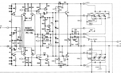
The voltages at IC101,pins 7,8 set the threshold for DC detection.
I'd have to calculate what they were designed to be or you can measure them.
D101,102,106,107 are 10V zeners and divided down using R106[109]@22k & R107[108]@3k9, so that works out to be ~1.5V.
Need to check all your voltages.
I'd have to calculate what they were designed to be or you can measure them.
D101,102,106,107 are 10V zeners and divided down using R106[109]@22k & R107[108]@3k9, so that works out to be ~1.5V.
Need to check all your voltages.
Was it the same problem as you have now?I was having problems with my amp that had the old style driver boards without offset adjustment pot.
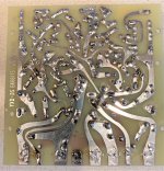
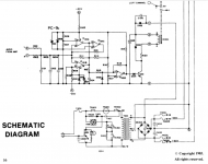
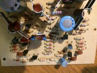
Yes main voltages are good and I can bias the outputs to 350ma. The protection board that is in the amp now is on a PC-9 board, from the original old boards. I know Hafler used a PC-9C on the driver boards I have installed now. They are slightly different. I would not think the protection circuit would be the problem? Here is a photo of the driver board and a schematic of the old protection circuit I am using and the newer one I am not using.
Attachments


Like I said, previously, time to start measuring voltages.
I see the heatsinks, for VAS and drivers, are missing in your pic. I assume you attached them before powering up, @+/-90V they will get really hot without them.
I see the heatsinks, for VAS and drivers, are missing in your pic. I assume you attached them before powering up, @+/-90V they will get really hot without them.
I removed heat sinks so that you can see orientation of transistors. Schematic does not indicate voltages.
Could be input grounding. Are connections made from board location 2 to input jack ground and to central ground?
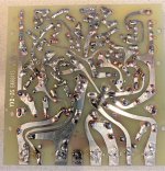
Clean off the flux on the PCB and check with a good lens for solder tails shorting between traces?
Okay, that was a good idea.I removed heat sinks so that you can see orientation of transistors. Schematic does not indicate voltages.
Too bad they did not right down the important voltage readings, in the schematic but in analyzing the design, one can figure what they should be approximately.
You could scan in a copy of the schematic, with your voltage readings written down for us to look them over.
Look around the offset adjust circuitry. Voltage at the base of Q3,5?
See what is up with that offset detection ckt not releasing the relay?
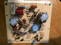
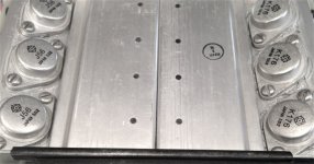
I just pulled 4 of those pcb's from a DH-200 that I have been modifying with a new design, here are a few pics of the PC-6A, might not be of use to you, but maybe someone else.
Attachments
Last edited:
Clean off the flux on the PCB and check with a good lens for solder tails shorting between traces?
Looking at the board photos that were posted, you can tell this board's been through quite a bit of soldering and parts changes. I've marked the suspicious joints with red circles. Some may be the camera angle, others might be shadows but I think I would suggest a thorough reflow and check of the soldering.
Attachments
Last edited:
Rudes
I have a few working DH500 amps with pc19c boards - if you need any specific measurements.
I have a few working DH500 amps with pc19c boards - if you need any specific measurements.
Thanks for replying guys!
As stated, I just purchased the boards blank and installed new parts. No parts changes. It's weird that both channels have the same problem and the fact the relay closes with all that offset. Also, bias pot does bias the outputs. I will check grounds, re-solder and clean pc.
As stated, I just purchased the boards blank and installed new parts. No parts changes. It's weird that both channels have the same problem and the fact the relay closes with all that offset. Also, bias pot does bias the outputs. I will check grounds, re-solder and clean pc.
Last edited:
Rudes
Did you measure the DC offset with a DMM or a scope ? When I had a similar problem with a DH500 - it was due to the amp oscillating like an atomic clock. I initially measured the DC with a cheap multimeter - and didn´t bother to check with a scope - so I was chasing my tail for some time before realizing the actual problem.
Since your problem was evident before the new boards - and on both channels - I´d suspect something on either the pc9 protection board or a short to ground somewhere. Check the main power caps for good measure.
Mind you - it might be a synergy of things causing this - so check everything 🙂
Hi guys,
OT, but since you have the covers off your DH-500, are you able to measure the clearance between the bottom of the pcb and the aluminium bracket surface underneath, in which the fets are mounted too? in mm pls.
FYI it is for a new OPS design to go along with the new DH-220C front end amp (AFE). We have it working in DH-200/220. The DH-500 would require a different OPS pcb to accommodate the 3 pairs and allow one to use this re-design in a different chassis as well.
On the troubleshooting note, when we re-designed the DH-220C, we put in provisions to test out the AFE stand alone. This was done by splitting the VAS buffer emitter resistor in half, use two and wire in series to make the same res value as if you were only using one. The center point can be used as a Test point and a place to FB to the IPS. You need to isolate the fet sources for the FB, we used a jumper block for this to make it easy.
You can do the same with the PC-19 pcbs you have. Probably best to short the fet gates to sources or ground, as floating gates on fets is never a good idea.
Thanks and good luck
Rick
I did NOT have the Offset problem with the old boards. Offset was only 17mv before I developed other problems that took out some components on the driver boards as well as some outputs.
Don't know if this matters, I also replaced all the outputs with NOS Hitachi.
Don't know if this matters, I also replaced all the outputs with NOS Hitachi.
That could have been costly, from the prices I see on eBay.Don't know if this matters, I also replaced all the outputs with NOS Hitachi.
Not that I can tell if they are your issue or not.
Two issues come to mind, matching and are they genuine?
I would recommend to use Exicon devices vs NOS. One is a trust factor, the other is if you can buy them matched?
I do not have experience with the Exicon devices, I will be trying them out shortly when my shipment arrives.
I would put down money that the new output transistors are the issue. And I agree that Exicon would be the only option for new laterals. Just follow rsavas advice to the letter - he is extremely well versed in these boards.
OT to rsavas; - it´s 24.5 mm from top of the board to the heatsink - note that the bottom of the laterals extrude at an angle towards the pcb - so there is less clearance at the edges.
Thx @parabolic, tighter than I thought on height for clearance.
I am going to PM you and take our conversation off this posting.
I am going to PM you and take our conversation off this posting.
- Home
- Amplifiers
- Solid State
- Hafler DH500 DC Offset