I already explained to you how to test out the front end.Is there anyway for me to confirm this before installing Exicons? I would not want to damage these!
Unknown?I am using Protronix thermal paste.
Either use the Wakefield white paste, just like they used originally or make it easy for yourself and just use good quality thermal pads.
Always check for TO-3 cases to heatsink with an ohmmeter for shorts. Could do the same for the other two pins as well.
They are mosfets, the case is the source.The cases of TO3 transistors are also the collectors.
Is there anyway for me to confirm this before installing Exicons? I would not want to damage these!
The method descibed by rsavas for front end testing is fully valid. I am a little worried though -that if you are not careful; you could do more harm then good.
Are either of the old pc19 boards (without offset pot) still working ? ... If so - build one channel with the old board and the chinese mosfets. It is absolutely vital to ramp up slowly with a variac and a current limiter/bulb.
From that you could deduct if the new mosfets or the new front end board is the offender. The voltage ramping would also offer insight into the protection board behaviour.
Seeing that your source for those output transistors is chinese - I can guarantee that they are fake - unless they are obvious pulls from scrap gear. Even with genuines - you would need them matched.
There was another thread where someone bought cheap Chinese laterals and when tested on a component analyser where in fact vertical mosfets !
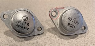
New Mosfet on the left, old original on the right. What do you guys think? Feel about the same weight.
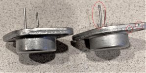
Actually there are several hints the ones on the right might have been recovered parts ... taken from other devices.
Yeah, more annoying red circles... 😉
Attachments

Another thing you can do is test with only one pair installed.
So I would just need one 2SK176 and one 2SJ56 installed on each channel? If that's the case I can try with some of the old mosfets that I have and test each channel separately. I was just using a variac before. I will build the light bulb current limiter and use both.
Actually there are several hints the ones on the right might have been recovered parts ... taken from other devices.
Yeah, more annoying red circles... 😉
The ones on the right are original. I purchased the amp new as a kit 31 years ago.
Hi guys,
OT, but since you have the covers off your DH-500, are you able to measure the clearance between the bottom of the pcb and the aluminium bracket surface underneath, in which the fets are mounted too? in mm pls.
FYI it is for a new OPS design to go along with the new DH-220C front end amp (AFE). We have it working in DH-200/220. The DH-500 would require a different OPS pcb to accommodate the 3 pairs and allow one to use this re-design in a different chassis as well.
On the troubleshooting note, when we re-designed the DH-220C, we put in provisions to test out the AFE stand alone. This was done by splitting the VAS buffer emitter resistor in half, use two and wire in series to make the same res value as if you were only using one. The center point can be used as a Test point and a place to FB to the IPS. You need to isolate the fet sources for the FB, we used a jumper block for this to make it easy.
You can do the same with the PC-19 pcbs you have. Probably best to short the fet gates to sources or ground, as floating gates on fets is never a good idea.
Thanks and good luck
Rick
Rick, I appreciate your time and input, but I am a novice when it comes to troubleshooting and not familiar with some of the abbreviations or the technique you described. Is there another way you can explain?
The ones on the right are original. I purchased the amp new as a kit 39 years ago.
Okay, in more manageable terms.
In order to test the PC-19c pcb on its own, you need to close the feedback loop(FB). You can do this by replacing R33(220ohm,0.5W) with two (110 ohm,0.25W) resistors, connected in series. The mid point between the two, 110ohm resistors can be connected as your FB to the connection labeled as "B" on the schematic, this will close the FB loop.
Just make sure when you do this, that the output stage (OPS) mosfets are not installed.
Once this is done, you can test the PC-19c on its own. You can check bias voltages, apply signals to the input and measure the signal at "B", usually using an o'scope.
Good Luck Rick
Okay, in more manageable terms.
In order to test the PC-19c pcb on its own, you need to close the feedback loop(FB). You can do this by replacing R33(220ohm,0.5W) with two (110 ohm,0.25W) resistors, connected in series. The mid point between the two, 110ohm resistors can be connected as your FB to the connection labeled as "B" on the schematic, this will close the FB loop.
Just make sure when you do this, that the output stage (OPS) mosfets are not installed.
Once this is done, you can test the PC-19c on its own. You can check bias voltages, apply signals to the input and measure the signal at "B", usually using an o'scope.
Good Luck Rick
Thanks Rick! Unfortunately all I have is a digital multimeter. I can certainly measure voltages. Do you know if there is anything out there showing the schematic with voltages?
A DMM will have to do. I do not know of anything out there with voltages, but like I said earlier, they can be calculated, based on the values, knowing the supply V and circuit op.
The design can also be simulated which would provide the approx. voltages but that is another learning curve for you and not needed for what you are doing.
Mark up a schematic with what you measured and post it for review. Voltage measurements with respect to ground.
The design can also be simulated which would provide the approx. voltages but that is another learning curve for you and not needed for what you are doing.
Mark up a schematic with what you measured and post it for review. Voltage measurements with respect to ground.
Last edited:
Mark up a schematic with what you measured and post it for review. Voltage measurements with respect to ground.[/QUOTE]
So I'm going to close the feedback loop and measure with no outputs installed?
So I'm going to close the feedback loop and measure with no outputs installed?
So I'm going to close the feedback loop and measure with no outputs installed?
Yes, its gets you something you can power up without blowing outputs.
You can then probe for voltages and find where the fault is.
Its a standard trick with class ab amps. They feedback output into LTP to close the loop.
Rudes, when messing with these amplifiers, it is best to do initial power up with a dim bulb tester, used to detect shorts or malfunctioning equipment. I usually use a >=100W incandescent lamp. My unit has an AC power switch and a switch that shorts out the lamp.
Once the lamp dims down, big ecaps charge up, you know that there is not a dead short, then it safe to run full power.
Once the lamp dims down, big ecaps charge up, you know that there is not a dead short, then it safe to run full power.
Hey Guys it's been awhile. So I finally got around to doing some things. I noticed the old protection circuit was slightly different than the later design. So I changed those components. I cleaned the driver boards and checked soldering. I installed one board and ONE pair of the original outputs and used a test lamp and variac to slowly turn on the amp. There were no explosions or smoke. The outputs are warm. Should I set bias for 350ma the same as you would three pair to test voltages? The other thing is that the relay is not clicking on. Does this have anything to do with not having all the outputs installed? What points should I take voltage measurements from?
If the dc offset is now able to be adjusted rather than leaving us to assume such you should verify this by stating the measurements.
OK...Now I am able to adjust the DC offset down to 1mv and the relay kicks on. Don't know if it works because I used a pair of the old original outputs. I can not adjust the bias up to 350ma. Is this because I am only using one pair of outputs?
With only one pair you need to cut the bias by 2/3s, say 120ma or so. With only one pair installed it's for TESTING PURPOSES ONLY, DO NOT TRY TO DRIVE A LOAD TO FULL POWER!!!!!!!!
Craig
Craig
Last edited:
With only one pair you need to cut the bias by 2/3s, say 120ma or so. With only one pair installed it's for TESTING PURPOSES ONLY, DO NOT TRY TO DRIVE A LOAD TO FULL POWER!!!!!!!!
Craig
Thanks Craig.
But is it normal that I can not adjust it that high with the one pair?
- Home
- Amplifiers
- Solid State
- Hafler DH500 DC Offset