Someone definitely messed around with the switch wiring! You have it right now.
As for the rest of the primary wring, I'm not sure. I normally don't examine factory wiring unless I find a problem. Then I wouldn't remember each model years wiring down the road anyway unless it caused me grief.
As for the rest of the primary wring, I'm not sure. I normally don't examine factory wiring unless I find a problem. Then I wouldn't remember each model years wiring down the road anyway unless it caused me grief.
When I installed my new switch it needed to be wired differently than the original part, the terminals are not in the same positions. Pita having the free capacitor wires that were wrapped around the terminals.
I designed a simple soft start pcb that fits on the chassis, where the terminal strip is located, if someone wants it you can order blanks from jlcpcb and get the parts at mouser and digikey.
I designed a simple soft start pcb that fits on the chassis, where the terminal strip is located, if someone wants it you can order blanks from jlcpcb and get the parts at mouser and digikey.
Last edited:
Hi Rick,
When I see you maybe yo can show me what you put together. It doesn't have to be complicated at all.
Yeah, switch wiring isn't a standard at all. Lots of fun!
-Chris
When I see you maybe yo can show me what you put together. It doesn't have to be complicated at all.
Yeah, switch wiring isn't a standard at all. Lots of fun!
-Chris
I will bring both the Hafler and bc-1 to Dave’s on Sunday. It would be fun to see if we can hear any differences.
I was going to ask if anyone had used one of the little china made soft start boards, there are heaps of them on ebay and aliexpress, 10-20 bucks will get you one thats supposedly rated to 100A.
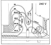
Here is the picture from the manual of the wiring for 240v region. If someone could explain what the jumper does exactly? I measure 120v from the jumper's switch terminal to neutral. I guess that means the BR - BK/W connection is two 120v primary taps joined for 240v.
I was thinking of adding a fuse so both active & neutral are fused.
So you dont think its a good idea to have a thermistor just before the switch? I found a 3 ohm 7A rated one here and fitted it on its own tag strip, its sitting in the open with a good half inch or more space around it.
I fitted a new 0.047uf X cap across the new switch rather than try removing the old one! (old switch was fine, but not exact size, a bit narrow for the cutout).
Attachments
I measured old switch and new switch and terminals were the same, I wired the new one in the same as the old one (after I had rewired the old one identical to the drawing I posted above and tested the amp) but I reversed the active/neutral so active was running through switch after the fuse, and neutral direct to the PT. Thats when my light stayed on!When I installed my new switch it needed to be wired differently than the original part, the terminals are not in the same positions.
So does that mean the old switch, centre pin was not connected to the light circuit, it was pin one, but in the new switch the light circuit must be connected to the centre pin (2)? So having the active feeding into the centre pin (as pre drawing) was powering the light constantly, even though the circuit itself was not powered, due to the neutral feeding the jumper wire back to pin 3 of the switch?
Im sure I see all this in my mind and its correct but doubt is a bastard! 😀
The jumper is for the lamp.
The thermistor is the old way of limiting inrush current. Your soft start board replaces it entirely. Don't use both, the soft start PCB with relay is much better.
Do not worry about the hot and common (phase). Just interrupt the hot side, that's about it.
The thermistor is the old way of limiting inrush current. Your soft start board replaces it entirely. Don't use both, the soft start PCB with relay is much better.
Do not worry about the hot and common (phase). Just interrupt the hot side, that's about it.
thanks, I will leave the thermistor there for now while I look into soft start boards, will swap it out once I get to that stage.
our AC standards follow the MEN and CMEN principle for earthing, I imagine Canada is the same?
I'm going to put a new chassis earth behind the main caps centrally, then isolate the tags on the heatsinks with nylon bolts n washers, run the earth back to one point.
I planned to use a 3 core shielded cable for the input, using 2 of the wires for the neg, connected together at the board, and one at the rca end, the other going to the new earth point through a 10 ohm resistor, am I on the right track here? it was described easy back in this thread but no pics o could find.
I wouldn't change the ground points from factory without a very good reason.
The wiring for signals and ground are normally arrived at through careful design and experimentation. Especially how the grounds run. You stand the very real risk of creating a hum or buzz.
The wiring for signals and ground are normally arrived at through careful design and experimentation. Especially how the grounds run. You stand the very real risk of creating a hum or buzz.
Since we are talking about Hafler amps, what do you guys think about the design of the Pro 2400 ?
https://manualzz.com/doc/7458733/hafler-pro-2400-amplifier-manual
I was offered a pro 2400 for not that much, having a xl-280 I am on the fence about the 2400.
The 2400 uses Toshiba lateral, is the 2400 an improvement over the DH-220 ?
https://www.diyaudio.com/community/attachments/img_0085-jpg.377340/
I would grab it.
It has a very good voltage amp section and proper drive for the output mosfets. For all intents, the output drive is similar enough, but the voltage amp is really nice. They are all good output mosfets, don't sweat what people light say on the 'net.
It has a very good voltage amp section and proper drive for the output mosfets. For all intents, the output drive is similar enough, but the voltage amp is really nice. They are all good output mosfets, don't sweat what people light say on the 'net.

Sorry for the late update. Work completely consuming me for a while. Still trying to solve the right channel sawtooth distortion and motorboating. All component changes suggested earlier have been done to no avail. Though they are new I am going to replace Q1 and 2. The sawtooth distortion is evident there, though I don know if that is conclusive since the feedback circuit could be to blame as well. Don’t have enough circuit theory knowledge to be sure. I will report back when I get the chance. Thanks for the advice.Hi Jeff
Has this problem been fixed now.
if not, this seems like a “motorboating“ issue. You can search the web for explanations. These may be difficult to fix in a new amp but this one has been design proven for years…
From my humble experience, in these situations it can possibly be fixed by securing again all your grounding connections (even RCA plug ground sometimes not doing a very good connection) or revisit your grounding scheme….
Fab
iirc you get a sawtooth wave form when the fuse is open, the FB is run thru the components that are in parallel with the fuse, iow it creates an integrator.
well the DH200 is back together, I ended up replacing all the resistors that were listed in various posts in this thread, the ones around the transistors.
I think I might have some trannies that are slightly off, left channel 44mv, right channel 8mv.
have set the bias at 290-300ma. it's only on the bench right now with some ceiling speakers to check it with, I have 2 meters on the outputs looking at the offset, and one on a channel watching bias.
it's very quiet through the speakers, have to stick you ear against one to hear anything, so that makes me happy, just the offset on left channel to get lower now.
update, was getting some crackling through the left side when moving the new shielded input cable around, moving the edge of the board side to side slightly had the dc moving up and down, went down to 25mv, then right down then up, seems something not quite right. unscrewed the sink and board and looked it over again, went over solder joins that looked like I hadn't touched them, cleaned it and put back together, now I have 50mv!
any suggestions as to what I have missed? right channel still at 7mv +/-.
it does sound good even all new, quite a delicate touch, needs some hours on it, the big kemet caps likely need a few hours.
Turn on seems gentle enough, the thermistor only gets warm though, is this normal? I thought they get quite hot.
Rick,iirc you get a sawtooth wave form when the fuse is open, the FB is run thru the components that are in parallel with the fuse, iow it creates an integrator.
I restored the fuse network back to stock some time ago and all fuses are intact. The sound improved, but only marginally and the sawtooth wave on the positive side of the RH channel output remains at frequencies above about 2.5khz, and power above about .05 watts. It is everywhere in the positive circuit after Q1 and Q2. They are new as are nearly everything else on the board. My rookie mind says replace Q1 and 2 again, but thought I’d wait until more experienced minds chimed in.
I also replaced the caps on the mosfets with the appropriate types as suggested, as well as reducing C1 to 390uf. No change resulted.
yes that was next on my list 🙂Hi Sonic Art,
Match the complementary differential pair!
prefect timing my 30 "fairchild" 5401/5551 pairs arrived yesterday, last night I measured them all with my trannie tester, I did 4 test runs on each device to keep the tester active and settled, matched the hFe and Vf and ended up with 2 groups for the 5551, and 5 groups for the 5401.
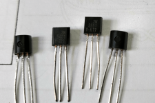
I have posted a pic of the ic's in case anyone recognises them as Fairchild? supposed to be genuine old stock? or are they still making them?
just now I finished replacing Q1-6 with my matched parts, and am now looking at -4-5mv on the left channel, +6-7mv on right. that sound ok?
wondering should I do the right channel as well so the amp has mirror imaged parts? for the sound 😉
and the other 3 ic's on the board while I'm in the mood and it's apart? 😀
Attachments
- Home
- Amplifiers
- Solid State
- Hafler DH-200/220 Mods