Re: DH-220 Mods, PA3 Boards Installed
this file will be there for some time:
http://czsr_bac.on.neobee.net/mainsdelay.pdf
besides that,you can always use thermistor ........CL60.....as Papa Nelson for his amps
tincanear said:............
Does anyone know of a soft-start module available? I'm thinking of adding a replacing diode bridge (a pair 20A schottky setups-- one per channel) and adding 2 more main filter caps to allow dual mono operation.
.............
-Bruce
this file will be there for some time:
http://czsr_bac.on.neobee.net/mainsdelay.pdf
besides that,you can always use thermistor ........CL60.....as Papa Nelson for his amps
Re: Re: DH-220 Mods, PA3 Boards Installed
hmmm ....
has anybody actually done this for haflers or any other class ab amp?
pass's amps are highly class a.
i'd use a timed relay to short the CL60 or a regular power resistor after "a short time".
mlloyd1
hmmm ....
has anybody actually done this for haflers or any other class ab amp?
pass's amps are highly class a.
i'd use a timed relay to short the CL60 or a regular power resistor after "a short time".
mlloyd1
Zen Mod said:...
besides that,you can always use thermistor ........CL60.....as Papa Nelson for his amps
Re: Re: Re: DH-220 Mods, PA3 Boards Installed
you are right.........I just sometimes forget that Hafler isn't class A,even if my specimen was pretty hot.........in time when I have one 😉
so-plain WW or termistor ,with shorting relay across 😉
mlloyd1 said:hmmm ....
has anybody actually done this for haflers or any other class ab amp?
pass's amps are highly class a.
i'd use a timed relay to short the CL60 or a regular power resistor after "a short time".
mlloyd1
you are right.........I just sometimes forget that Hafler isn't class A,even if my specimen was pretty hot.........in time when I have one 😉
so-plain WW or termistor ,with shorting relay across 😉
thanks for the prompt replies (i'm surprised that so many are watching this thread). i had seen the w.w. resistor with time delay relay idea before, but i didn't like the idea that the resistors could overheat / flame out (at 10 ohms, power ~ 1000W) if relay didn't close, but using NTC thermistor AND a time delay relay sounds like the best combo. i forgot to mention that my DH220 also has 625W toroid (has dual center-tapped secondaries, MC unit from about 10 years ago) and the lights in the room dim briefly when its turned on, plus the power switch is getting a bit unreliable as well now...
who is the manufacturer of the CL60 thermistor?
thanks,
Bruce
who is the manufacturer of the CL60 thermistor?
thanks,
Bruce
mmerig said:Here is a summary of how the voltage regulator in my Hafler 220 worked out.
...First I used sine wave tones (20, 40, 100, 500, 1k, 8K, 10K, 12K, 15K, 18K, 20K). I also used short clips of music with big transients. Each sequence was a few seconds, repeated several times for about 30 seconds total. The first clip was a hammer on steel (from Johnny Cash's "The Legend of John Henry's Hammer"), the second was the first drum beat from B. Dylan's "Like a Rolling Stone", the last was a bass-heavy section from Jack Johnson's "Wasting Time".
The last track was symbolic for the whole effort, as I hardly heard a difference on any test, except a subtle one on the hammer track. The volume was as loud as I could stand, and I blew two speaker fuses.
When I took out the regulator, I tested it and realized that the LM337 had broken on the negative rail. The 33 volt zener was also broken. C4 (0.1 uf, 630V, film) looked like it got warm, as the wound label had distorted. The output voltage was about 80 volts rather than the desired 70. So there are still some reliability issues. There is no short circuit protection on the regulator, but other than low resistance as capacitors are charging, I cannot think of what would cause this problem. There is only about 500 uf on each rail after the regulators.
...
Because of these problems, I learned alot, and that was the main reason for doing this. Thanks to all that helped me. Any further comments or questions are welcome.
Hi mmerig
I suppose that you did not connect the regulated voltage on the mosfet drain...because the current at high output will destroy for sure the LM337/317.🙄
Based on your sayings, since one regulator was broken you may have not really tested your amp with regulated voltage on the front end circuit. ..

Also, I am not sure that you need to test sound at so high volume...😉
Originally posted by FAB
FAB, thanks again for your comments. You are correct, I did not connect the regulator to the main mosfet drain. Please see post # 277 on this.
Also, my test was somewhat faulty because of the broken regulator on one rail, but there was still a separate supply for the front end (including transformers), so if there was a voltage sag in the main supply, it would not show up in the front end.
I listened to the amp at normal volumes and heard no difference. I figured the benefits of the regulator would be for big transients, and tested it loud because I figured if there was any voltage sag on the main supply, it would happen at higher volumes.
Now that I have rebuiilt the regulator, I will try it again. Maybe I did comething inadvertantly to break the LM337 while installing it.
By the way, the difference in ripple current (post #271) was an artifact of my meter, which is apparently faulty for AC voltage. There may be some high harmonics that "fool" the meter.
Hi mmerig
I suppose that you did not connect the regulated voltage on the mosfet drain...because the current at high output will destroy for sure the LM337/317.
Based on your sayings, since one regulator was broken you may have not really tested your amp with regulated voltage on the front end circuit. ..
Also, I am not sure that you need to test sound at so high volume...
FAB, thanks again for your comments. You are correct, I did not connect the regulator to the main mosfet drain. Please see post # 277 on this.
Also, my test was somewhat faulty because of the broken regulator on one rail, but there was still a separate supply for the front end (including transformers), so if there was a voltage sag in the main supply, it would not show up in the front end.
I listened to the amp at normal volumes and heard no difference. I figured the benefits of the regulator would be for big transients, and tested it loud because I figured if there was any voltage sag on the main supply, it would happen at higher volumes.
Now that I have rebuiilt the regulator, I will try it again. Maybe I did comething inadvertantly to break the LM337 while installing it.
By the way, the difference in ripple current (post #271) was an artifact of my meter, which is apparently faulty for AC voltage. There may be some high harmonics that "fool" the meter.
Regulated front end
Mmerig,
Maybe you expect too much of this mod. Anyway, have in mind that you need a good recording, a good source player and a good pre-amp that do not hide the details. The difference is subtle like hearing more the voice echo done in the mixing, distinguing more clearly several different voices in a choral, ...
mmerig said:Originally posted by FAB
...
Also, my test was somewhat faulty because of the broken regulator on one rail, but there was still a separate supply for the front end (including transformers), so if there was a voltage sag in the main supply, it would not show up in the front end.
I listened to the amp at normal volumes and heard no difference. I figured the benefits of the regulator would be for big transients, and tested it loud because I figured if there was any voltage sag on the main supply, it would happen at higher volumes.
Now that I have rebuiilt the regulator, I will try it again. Maybe I did comething inadvertantly to break the LM337 while installing it.
...
Mmerig,
Maybe you expect too much of this mod. Anyway, have in mind that you need a good recording, a good source player and a good pre-amp that do not hide the details. The difference is subtle like hearing more the voice echo done in the mixing, distinguing more clearly several different voices in a choral, ...
Perhaps my assumptions were wrong about what the regulator is supposed to do:
Provide a separate power supply to the voltage amplifier stages that stays costant when current draw is high on the main power supply to the output devices. The regulators provide stable voltage, and the capacitors improve transient response and help smooth ripple current.
Given this, when playing music without big transients (especially bass), I would not expect much difference between an amp with one power supply for both VAS and outputs, than one with a separate regulated supply for the VAS.
My amplifier sounds fine w/o the regulator, and building the regulator was more of an experiment and learning experience for me than the ultimate quest in sound. Of course I thought it would improve it some, and it may eventually. I am much more curious about than disapointed with my results.
Originally quoted by FAB
Why would a regulator improve imaging, details, etc. if the power supply is simply clean and stiff with an adequate transformer, capacitors, and maybe some extra-quiet rectifiers? This is intriguing. Could you please elaborate or point me to information?
Thanks again.
Provide a separate power supply to the voltage amplifier stages that stays costant when current draw is high on the main power supply to the output devices. The regulators provide stable voltage, and the capacitors improve transient response and help smooth ripple current.
Given this, when playing music without big transients (especially bass), I would not expect much difference between an amp with one power supply for both VAS and outputs, than one with a separate regulated supply for the VAS.
My amplifier sounds fine w/o the regulator, and building the regulator was more of an experiment and learning experience for me than the ultimate quest in sound. Of course I thought it would improve it some, and it may eventually. I am much more curious about than disapointed with my results.
Originally quoted by FAB
Maybe you expect too much of this mod. Anyway, have in mind that you need a good recording, a good source player and a good pre-amp that do not hide the details. The difference is subtle like hearing more the voice echo done in the mixing, distinguing more clearly several different voices in a choral
Why would a regulator improve imaging, details, etc. if the power supply is simply clean and stiff with an adequate transformer, capacitors, and maybe some extra-quiet rectifiers? This is intriguing. Could you please elaborate or point me to information?
Thanks again.
Regulated front end
I agree that isolating the front end and the output stage with different supply is probably the biggest improvement assuming that you have a good filtering of the supply of the front end. Regulating this front end supply is just a step further to limit the power supply voltage modulation even more upon large amplitude music signal.
You must also consider that in my DH-200 amp sI did not use separate power supply for the front end (no place to add another transfo, bridge and 100Vdc hi cap values) but only regulators to "isolate" the front end supply from the outputs stage power supply modulation with music. Doing just that, improved the sound based on comments from the peoples who have heard my amp before and after the mod without knowing I did a mod...
In my "big" amp (see my web site) I have the place to add both (separate transfo, bridge, caps and regulators) thus theoritically the best for audio nirvana quest. My goal is really to get the best sound as possible...😎 😉
mmerig said:...Why would a regulator improve imaging, details, etc. if the power supply is simply clean and stiff with an adequate transformer, capacitors, and maybe some extra-quiet rectifiers? This is intriguing. Could you please elaborate or point me to information?
Thanks again.
I agree that isolating the front end and the output stage with different supply is probably the biggest improvement assuming that you have a good filtering of the supply of the front end. Regulating this front end supply is just a step further to limit the power supply voltage modulation even more upon large amplitude music signal.
You must also consider that in my DH-200 amp sI did not use separate power supply for the front end (no place to add another transfo, bridge and 100Vdc hi cap values) but only regulators to "isolate" the front end supply from the outputs stage power supply modulation with music. Doing just that, improved the sound based on comments from the peoples who have heard my amp before and after the mod without knowing I did a mod...
In my "big" amp (see my web site) I have the place to add both (separate transfo, bridge, caps and regulators) thus theoritically the best for audio nirvana quest. My goal is really to get the best sound as possible...😎 😉
Musical Concepts PA-3D Problem
I have installed these new boards into my DH 500. The description can be found here: http://www.musicaldesign.com/mc_amp_mods.htm This modification can be done to the DH200/220/500 and other Haffler amps. These boards replace the drive boards on the original amp. The Mosfet circuitry is unchanged except for new film caps and stabilizing caps. My problem is after the installation only one channel worked correctly. The amp was functioning correctly prior to the upgrade.
The negative rail is -97.8 volts (122.5VAC to the transformer input) and the output from the bad channel is -96.3 volts and the drive voltage to both N and P channel Mosfets is also -96.3 volts. Musical Concepts is sending a new board, but I want to make sure that I have checked everything that could have caused this before putting the new board in.
It was suggested that I measure the drive resistors connected to the Mosfets and if the resistance was correct per the schematic, the Mosfets were probably OK. I did this and the resistances are correct. The Mosfets are supposed to be biased at 330ma, but on the bad channel, there is no current draw at all.
Are there other tests that I should perform on the Mosfets? Is there anything else I should look for? I have checked and rechecked the wiring, soldering and have looked for solder bridges and solder splashes. Any help is appreciated.
Lindsay
Are there other tests that I should perform on the Mosfets?
My guess is that the MOSFET's are okay, but you should test them to be sure. For a method, try this:
http://www.passdiy.com/howto/matching.htm
The MOSFET checking "recipe" from Nelson Pass is for vertical MOSFETs, not the lateral Hitachi devices used in Hafler amps.
There are guys here more astute than me that can tell you how to adjust the voltages in Pass's formulation, but don't apply it to lateral MOSFETs without modification.
There are guys here more astute than me that can tell you how to adjust the voltages in Pass's formulation, but don't apply it to lateral MOSFETs without modification.
Dick and mmreg, thanks for the replies.
I received the replacement board from Musical Concepts and it appears to have the same problem. I did not put the B+ and B- fuses in so there was no power to the MOSFETS, but there was power to the board and the board was connected to the drive and output connections of the MOSFETS.. The good board (right channel) has three LEDs and all three light up under the same conditions. The other board (left channel) only two light up. Since no power is connected to the MOSFETS There must be something wrong relative to the drive on the MOSFETS. I sure wish I'd paid attention when my dad tried to each me electronics.
The only other change to the circuit was the addition of two capacitors across one each of the P channel and N channel MOSFETS. Since so little has changed I am thinking there is some problem with the new board driving these particular MOSFETS, i.e. there is something wrong with one or more of the MOSFETS. Before making changes, there was a 0.3 VDC offset in the channel that now does not work. I could not adjust the offset pot on the old board enough to get rid of the offset.
If the MOSFETS are indeed bad, is there any hope of finding replacements?
Lindsay
LHM Audio
By "the drive voltage to both N and P channel Mosfets is also -96.3 volts." do you mean the voltages that go to the drains of the output MOSFETs? The drive voltage to their gates should be around 1 volt, with no signal present.
By "the drive voltage to both N and P channel Mosfets is also -96.3 volts." do you mean the voltages that go to the drains of the output MOSFETs? The drive voltage to their gates should be around 1 volt, with no signal present.
Dick,
Exactly, by leaving out the fuses which are mounted on the boards, the 96 volt plus and minus go to the drive board but not to the MOSFETS. Only the MOSFET drives and outputs are connected. I did not measure voltages as I only had a few minutes to check it out. But since there is no high voltage to the MOSFETS I suspect there is only low voltage on the drive and output.
Exactly, by leaving out the fuses which are mounted on the boards, the 96 volt plus and minus go to the drive board but not to the MOSFETS. Only the MOSFET drives and outputs are connected. I did not measure voltages as I only had a few minutes to check it out. But since there is no high voltage to the MOSFETS I suspect there is only low voltage on the drive and output.
Originally posted by LHMAudio
Don't these fuses apply to the rails, and if they are out, there is no voltage to either the board or the MOSFET's? Have you tried it with the fuses in?
Originally posted by Dick West
Dick West's cautionary statement is well-warranted. Following Nelson Pass's directions exactly could cause a problem, if the gate-to-source breakdown voltage for the Hitachi MOSFETS is exceeded. The G-S voltage for the Hitachi 2sk56, 2SJ56 is 20; the voltage in Pass' example is 15. The IRFP240 MOSFETs that Pass uses also have a G-S breakdown voltage of 20 -- well-above the 15V in the test circuit. For the test, I don't think lateral versus vertical matters, but I would get a second opinion on this in the "Electronics and Parts" forum on the dyiAudio site. I have matched Hitachi MOSFET's out of a Hafler DH220 (2SJ49, 2SK134) using Pass' circuit with around 10 volts. These devices have a G-S breakdown voltage of 14. If these devices happen to be in your amp, then using 15 volts would probably break them.
The Hitachi's drain-to source breakdown voltage is between 120 and 200 (depending on the part number), so 98 V rail voltage should not have broken them. However, MOSFET's are sensitive to static electricity, and it is possible that a charge on your body broke them while being handled. There may have been problems before, as 0.3 volts of DC offset seems high to me. Is there something going on with the relay circuit that detects DC offset?
You could remove the MOSFETS's (unscrew their mounting screws) and check for shorts among the pins and the case (source), There should not be any. Make sure you keep track of the polarity (N-channel and P-Channel) for each socket. Do you have the data sheets for the MOSFET's? They are available and free on the internet.
It's risky to switch components around for a test, but if you are sure the good channel is working and your possibly-bad MOSFET's are not shorted, you can probably move the bad channel MOSFET's over to the good and see what happens. I would get a second opinion on moving them. You could put one of the original boards back in and see if the MOSFET's on the bad channel work with it. This would be my first choice if I did not have a MOSFET tester built already.
What does John Hillig think is going on?
The Hitachi MOSFET"S should still be available. Frank Van Alstine (http://www.avahifi.com/) may still have the higher voltage version (2SJ56, 2SK176, I think) to sell, and Soundvalves on Ebay should be able to sell you matched pairs; Email them and ask about it. Still, I'd b surprised if the MOSFET's are broken.
by leaving out the fuses which are mounted on the boards, the 96 volt plus and minus go to the drive board but not to the MOSFETS. Only the MOSFET drives and outputs are connected.
Don't these fuses apply to the rails, and if they are out, there is no voltage to either the board or the MOSFET's? Have you tried it with the fuses in?
Originally posted by Dick West
The MOSFET checking "recipe" from Nelson Pass is for vertical MOSFETs, not the lateral Hitachi devices used in Hafler amps.
Dick West's cautionary statement is well-warranted. Following Nelson Pass's directions exactly could cause a problem, if the gate-to-source breakdown voltage for the Hitachi MOSFETS is exceeded. The G-S voltage for the Hitachi 2sk56, 2SJ56 is 20; the voltage in Pass' example is 15. The IRFP240 MOSFETs that Pass uses also have a G-S breakdown voltage of 20 -- well-above the 15V in the test circuit. For the test, I don't think lateral versus vertical matters, but I would get a second opinion on this in the "Electronics and Parts" forum on the dyiAudio site. I have matched Hitachi MOSFET's out of a Hafler DH220 (2SJ49, 2SK134) using Pass' circuit with around 10 volts. These devices have a G-S breakdown voltage of 14. If these devices happen to be in your amp, then using 15 volts would probably break them.
The Hitachi's drain-to source breakdown voltage is between 120 and 200 (depending on the part number), so 98 V rail voltage should not have broken them. However, MOSFET's are sensitive to static electricity, and it is possible that a charge on your body broke them while being handled. There may have been problems before, as 0.3 volts of DC offset seems high to me. Is there something going on with the relay circuit that detects DC offset?
You could remove the MOSFETS's (unscrew their mounting screws) and check for shorts among the pins and the case (source), There should not be any. Make sure you keep track of the polarity (N-channel and P-Channel) for each socket. Do you have the data sheets for the MOSFET's? They are available and free on the internet.
It's risky to switch components around for a test, but if you are sure the good channel is working and your possibly-bad MOSFET's are not shorted, you can probably move the bad channel MOSFET's over to the good and see what happens. I would get a second opinion on moving them. You could put one of the original boards back in and see if the MOSFET's on the bad channel work with it. This would be my first choice if I did not have a MOSFET tester built already.
What does John Hillig think is going on?
The Hitachi MOSFET"S should still be available. Frank Van Alstine (http://www.avahifi.com/) may still have the higher voltage version (2SJ56, 2SK176, I think) to sell, and Soundvalves on Ebay should be able to sell you matched pairs; Email them and ask about it. Still, I'd b surprised if the MOSFET's are broken.
mmerig,
Thanks for your extensive reply. In the new boards, the fuses are on the board and only supply the MOSFETS. The driver board is always connected to the rails and is not fused. The MOSFETS were not removed during the upgrade so I would not think that static electricity would play a role, but never say never.
In my latest test I did not connect the input or output from the board, so the DC detection circuit is not connected to the board in any way.
I called John and he called back, but his message said he would be unavailable until Monday. I am going through serious withdrawal here and may need to resurrect an old Marantz power amp if I can't get the Haffler working.
I may try one of the old boards as that would give me a definitive answer.
Is it possible to remove one MOSFET at a time and test the circuit or will it provide too much bias current for the remaining MOSFETS? Of course this won't tell me if more than one is bad. Can one bank of MOSFETS be removed and test the circuit in some way?
Thanks for you help.
Lindsay
Your amp has 6 MOSFETs per channel, 3 P and 3N-channel devices. I suppose you could run a channel with only one P and one N, if the bias current were turned down appropriately. Do you have a Variac?
By reducing the number of devices per channel you could switch them around and thus perhaps locate the presumed faulty device. But, do this only when monitoring offset and bias and with reduced voltage from a Variac. But, keep the number of P and N channel devices the same, 1 to 1, 2 to 2, etc.
Mr. Hillig might have a suggestion about this as I know he has mentioned running another Hafler with fewer MOSFETs than originally designed.
Dick,
Thanks for the suggestions. Unfortunately I do not have a Variac. The best I can do is the light bulb in series with the AC line. I guess if I am going to be really serious about DIY I need a Variac, Oscilloscope and signal generator. Plus a lot more free time.
I guess I'll wait until Mr. Hillig gets back to me on Monday. Thanks again.
Lindsay
I got a cheap old panel mount Variac from an eBay auction, and mounted it in the metal case from an old large style AT computer power supply.
A Variac rated at 5 amps would be a good purchase. Some say one rated at only 3 amps is OK. We are not talking big bucks here, considering the cost of damaged parts that could be saved by using a Variac.
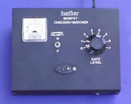
BTW, here is what I use the check and grade with numbers 1-7 the MOSFETs we use in amplifiers like the older Haflers:
A Variac rated at 5 amps would be a good purchase. Some say one rated at only 3 amps is OK. We are not talking big bucks here, considering the cost of damaged parts that could be saved by using a Variac.
BTW, here is what I use the check and grade with numbers 1-7 the MOSFETs we use in amplifiers like the older Haflers:
Attachments
- Home
- Amplifiers
- Solid State
- Hafler DH-200/220 Mods