battradio,
Interesting comments about the evolution of Hillig's business and your part in it.
The DH-200 keeps the speaker protection fuses in the feedback loop. Is this really advisable or should the loop's eyelets be jumpered and the fuse put in series with the output? Putting the fuse on the speaker itself is an interesting idea but I would have to do this on a lot of speakers I mess with. Keeping the fuse on the back of the amp is the easiest for me.
I agree on the failure prone input diff and bias transistors. On most of the 30 or so DH-200s I have fixed the last few years these have been the failure spots. Rarely does a driver or pre-driver transistor fail. And, never so far have I found a failed MOSFET output device.
Dick
Dick West said:Fab,
Nice circuit. Is there enough adjustment in it to allow it to work with the 75VDC of an XL-280 transformer? What component values would have to be changed?
. . .
No the previous shown circuit works around the suggested output voltage. It is simple but has its limitations.
For a better adjustment you can use this circuit instead. R5 and R8 could be reduced to about 5 ohms.
Attachments
Regulated supply
I was expecting an output voltage around 57.3volts from my circuit. But with an input of 60volts I guess I'm too close for proper regulation, unless my input is higher than 60volts. I will have to check the exact voltage with a meter, or reduce the value of my zener. Maybe I will need to include an adjustable resistor as you have done, Fab.
I realise that the LM317 is being used in a fixed mode, but I understand the performance to be superior to fixed type regulators.
The raw supply voltage drops like a rock under load.
The best thing to do is add a small 8V 100mA or so dual secondary transformer to the main Hafler windings, rectify and filter, then regulate. The Hafler XL series already have low current HV windings.
Digi-Key Part Number TE62010-ND Price Break
1
10
25
50
100 Unit Price
13.68000
12.16000
10.64000
9.72800
8.51200 Price
13.68
121.60
266.00
486.40
851.20
Manufacturer Part Number 62010
Description TRANSFRMR TOROID 7V .458A WIRES
Quantity Available 276
All prices are in US dollars
Regulated driver
Hi tchewtch,
First, the main line 120 Vac voltage vary in time so does the 60 Vdc output. I noticed in my DH-200 that it often varies between 58 to 61 Vdc even with no signal output voltage thus no load current.
Second, any power supply has a limitation in current handling capability. The main transformer has a reduced voltage under high current load than with no load. Check data sheet for transfo. The higher is the power of the transfo, the less it is affected by a gieven current load. I have not seen the spec of the DH-200 transfo but I have read somewhere that it is presumably about 475 VA. Added to the main transformer reduced voltage under loading, you have the AC ripple on the DC supply voltage. I have measured about 200 mV on the 60 Vdc of the DH-200 with no current load.
When you have 100 W rms load on one channel the supply voltage can measure as low as about 55 Vdc (excluding the ripple).
Since the voltage regulators (7818, Lm317) can work efficiently (regulate as per their spec) with at least about 3 V input voltage higher than its set output voltage, you should try to target more like 52 Vdc. You can also maje a compromise and use a higher voltage thus you will lose the benefit of regulate voltage only under high power of the amp.
The other alternative is to use an additional transfo winding to increase the input voltage of the driver section (as suggested by Dick West and djk) to be able to regulate to 60 Vdc but it adds further more to the complexity and the limited space inside the DH-200/220. You can have a look at the circuit below for a complete secondary regulated supply using a small second transformer instead of replacing the DH-200 transfo.
Good luck!
tchewtch said:I was expecting an output voltage around 57.3volts from my circuit. But with an input of 60volts I guess I'm too close for proper regulation, unless my input is higher than 60volts. I will have to check the exact voltage with a meter, or reduce the value of my zener. Maybe I will need to include an adjustable resistor as you have done, Fab.
I realise that the LM317 is being used in a fixed mode, but I understand the performance to be superior to fixed type regulators.
Hi tchewtch,
First, the main line 120 Vac voltage vary in time so does the 60 Vdc output. I noticed in my DH-200 that it often varies between 58 to 61 Vdc even with no signal output voltage thus no load current.
Second, any power supply has a limitation in current handling capability. The main transformer has a reduced voltage under high current load than with no load. Check data sheet for transfo. The higher is the power of the transfo, the less it is affected by a gieven current load. I have not seen the spec of the DH-200 transfo but I have read somewhere that it is presumably about 475 VA. Added to the main transformer reduced voltage under loading, you have the AC ripple on the DC supply voltage. I have measured about 200 mV on the 60 Vdc of the DH-200 with no current load.
When you have 100 W rms load on one channel the supply voltage can measure as low as about 55 Vdc (excluding the ripple).
Since the voltage regulators (7818, Lm317) can work efficiently (regulate as per their spec) with at least about 3 V input voltage higher than its set output voltage, you should try to target more like 52 Vdc. You can also maje a compromise and use a higher voltage thus you will lose the benefit of regulate voltage only under high power of the amp.
The other alternative is to use an additional transfo winding to increase the input voltage of the driver section (as suggested by Dick West and djk) to be able to regulate to 60 Vdc but it adds further more to the complexity and the limited space inside the DH-200/220. You can have a look at the circuit below for a complete secondary regulated supply using a small second transformer instead of replacing the DH-200 transfo.
Good luck!
Attachments
Fab,
You never cease to amaze me. Your picture of a regulator shows it to be a complete and well thought out circuit, complete with input AC filtering.
Do you ever publish etching templates for this PCB and a list of parts, in case one wanted to make one for himself?
The Audio Amateur (4/93 p16) has an article on making a dual mono set of front end regulators for the DH-220. Each channel's regulator was driven by ±85vdc and provided ±63vdc to the amp's front end PCBs. With these drops in voltage from 85 down to 63 the regulation should be rock solid.
Should anyone be serious about this project I have an extra Xl-280 transformer that can supply ±75vdc to the front end, which could be regulated down to ±60vdc.
One of your projects showed a pos and neg regulator that could be attached to the Hafler PCB as a "wing" and so fit into the stock chassis. Any more info about this little regulator circuit? I would like to etch and stuff the small PCBs for it if possible. There should be sufficient space on either side of the MOSFET pairs to accomodate a pos and neg regulator for each channel. Just a thought.
Dick West
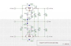
Front end Regulator board
Thanks djk.
Hello Dick,
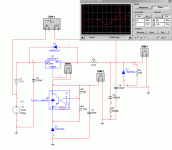
About the picture of the complete secondary power supply you will notice that it has been reworked with wires since it was originally intended for a voltage doubler circuit. The doubler circuit did not give the performance I was expected so I have adapted the board to include an additional transformer with double 12 Vac secondaries (to be added to each "positive" and "negative" windings of the main DH-200 transfo). However, even though I have not made the pcb, I have drawn an etching for the secondary transfo circuit. I can send you the gerber file if you want, just e-mail me. Here is attached the equivalent schematics circuit. I do not pretend it is the best one but it does the job. 75V and 68V zener diodes are only for protection in case of failure and are optional. In a preferred version, you can remove the 10V zener diodes and use 7824/7924 regulators. Pay attention to the added transfo primary windings connection orientation in respect ot the main DH-200/220 transfo primary. That is why I have indicated "+/-" on the windings.
For only the regulator section, I can send also the gerber file if the FitForm of the etching is as per your needs.
For the location of the regulator boards in my DH-200s, I have used each side of the main transfo for each channel with nylon glued post to attach the regulator boards. See the post #136 of this thread.
Good luck
Thanks djk.
Hello Dick,
About the picture of the complete secondary power supply you will notice that it has been reworked with wires since it was originally intended for a voltage doubler circuit. The doubler circuit did not give the performance I was expected so I have adapted the board to include an additional transformer with double 12 Vac secondaries (to be added to each "positive" and "negative" windings of the main DH-200 transfo). However, even though I have not made the pcb, I have drawn an etching for the secondary transfo circuit. I can send you the gerber file if you want, just e-mail me. Here is attached the equivalent schematics circuit. I do not pretend it is the best one but it does the job. 75V and 68V zener diodes are only for protection in case of failure and are optional. In a preferred version, you can remove the 10V zener diodes and use 7824/7924 regulators. Pay attention to the added transfo primary windings connection orientation in respect ot the main DH-200/220 transfo primary. That is why I have indicated "+/-" on the windings.
For only the regulator section, I can send also the gerber file if the FitForm of the etching is as per your needs.
For the location of the regulator boards in my DH-200s, I have used each side of the main transfo for each channel with nylon glued post to attach the regulator boards. See the post #136 of this thread.
Good luck
Attachments
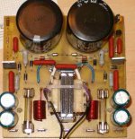
Front End voltage regulator
Dick,
Yes, it should be possible if you have good securing mounting means for the "Wings" pcbs.
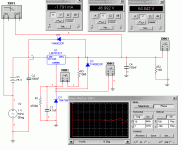
See attached info.
the resistors values can be adjusted to suit your voltage needs. Do not exceed 38 Vdc across TL431 and 37V across 78xx/79xx.
Good luck
Dick,
Yes, it should be possible if you have good securing mounting means for the "Wings" pcbs.
See attached info.
the resistors values can be adjusted to suit your voltage needs. Do not exceed 38 Vdc across TL431 and 37V across 78xx/79xx.
Good luck
Attachments
1) the resistors in series with the regulator output would seem to conflict with the purpose of the regulator.
more to say on the TL431 regulator later -- the standard Texas Instruments model breaks down unless it is used as a shunt regulator.
more to say on the TL431 regulator later -- the standard Texas Instruments model breaks down unless it is used as a shunt regulator.
jackinnj said:1) the resistors in series with the regulator output would seem to conflict with the purpose of the regulator.
more to say on the TL431 regulator later -- the standard Texas Instruments model breaks down unless it is used as a shunt regulator.
1) The resistor indicated is 10 ohms and is optional. It is used with the 470uF x2 as a low pass filter for residual ripple. I use 2.7 ohms with excellent results.
2) The TL431 is used as a SHUNT regulator in this circuit. The series regulator is the 7818/7918. The TL431 is used as a precision voltage reference to allow more than 37V at input of 78xx/79xx IC.
jackinnj said:The TL431 has reactive components which have to be compensated (not just the junction capacitance of a diode) -- TI's model isn't correct (and they are aware of the problem.)
Do you mean that the "spice" model is not correct or the TL431 design? TL431 has been used for years in many design circuits.
Do you mean that T.I. has a design issue?
Other manufacturers like On Semiconductor produce also the TL431.
What does your simulation shows?
Have you added compensation parts in the simulated circuit?
Thanks
Yes, Texas Instruments SPICE model on their site is not entirely correct, but there isn't a "design issue" with the device.
The TI SPICE models predicts the thermal performance wonderfully but doesn't model the error amplifier correctly. There was an article in the Design Ideas section of the Sept 15th EDN -- written by two TI engineers -- describing the compensation method. The TL431 is "ubiquitous" and it is a great, inexpensive chip to work with, it's just not the right device for this application.
I would just use the correct combination of zener diodes to determine the output voltage. 5 watt diodes are cheap and won't go pop. The bias to the diodes is set with a resistor to the "Ground" pin from the output terminal of the LM7818.
R = V(out)/(Ibias). figure 5 to 10 milliamps for the bias current. I show 10k in the attachment below -- too high a value -- but it's just for purposes of illustration.
We can make it a little more elegant...
Attachments
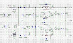
Voltage regulator
I still not see the relation between a wrong spice model and the real circuit performance. The main goal of using the TL431 is to replace the Zener diode and provide voltage adjustment. I have used a circuit as the one you have shown for 2 years but I wanted to do a more versatile circuit. Remember that "cheap" zener diode are 5% tolerance and 5W diode are not cheaper than a TL431 (70 cent). Since a positive and negative regulator are needed than the 2 zener diodes (one for each polarity) must be matched. The TL431 is a more precise voltage reference than a simple zener diode. From what I remember the performance (ripple) with the TL431 was in the same range as the one with only a zener diode. I believe that the performance for either circuit is good enough for the purpose of the application. Anyway, the pcb layout I have provided can use only a single Zener diode and no TL431 if required.
I still not see the relation between a wrong spice model and the real circuit performance. The main goal of using the TL431 is to replace the Zener diode and provide voltage adjustment. I have used a circuit as the one you have shown for 2 years but I wanted to do a more versatile circuit. Remember that "cheap" zener diode are 5% tolerance and 5W diode are not cheaper than a TL431 (70 cent). Since a positive and negative regulator are needed than the 2 zener diodes (one for each polarity) must be matched. The TL431 is a more precise voltage reference than a simple zener diode. From what I remember the performance (ripple) with the TL431 was in the same range as the one with only a zener diode. I believe that the performance for either circuit is good enough for the purpose of the application. Anyway, the pcb layout I have provided can use only a single Zener diode and no TL431 if required.
Re: Voltage regulator
You have inserted a "reactive component", the TL431 -- into the ground return of the linear regulator made worse with the 56nF bypass. Take out the 56nF for it is really problematic --
fab said:I still not see the relation between a wrong spice model and the real circuit performance.
You have inserted a "reactive component", the TL431 -- into the ground return of the linear regulator made worse with the 56nF bypass. Take out the 56nF for it is really problematic --
Re: Re: Voltage regulator
OK, I have checked more closely the datasheet on the Stability boundary conditions of the TL431. From my circuit with 7818/7918 it is more difficult to evaluate the problematic cathode current based on the curves provided in the datasheet. So far, I have built 8 circuits successfully but I agree that it would be more safe to remove the 56 nF cap across the TL431.
thanks for the observation.
jackinnj said:
You have inserted a "reactive component", the TL431 -- into the ground return of the linear regulator made worse with the 56nF bypass. Take out the 56nF for it is really problematic --
OK, I have checked more closely the datasheet on the Stability boundary conditions of the TL431. From my circuit with 7818/7918 it is more difficult to evaluate the problematic cathode current based on the curves provided in the datasheet. So far, I have built 8 circuits successfully but I agree that it would be more safe to remove the 56 nF cap across the TL431.
thanks for the observation.
DH220
Hello all,
Did somebody try to short capacitors C8 (and hence also C7)
in the Hafler DH-220 ?
I know that this capacitor increase the feedback in very low frequencies, below 3Hz, but I do not think that the amplifer
will get into oscllations while there will be sonic improvements.
Who need 470uF electrolytic capacitors which reduce the
sound quality! It is located really on the inverted input signal.
So, what do you think ?
Thanks, Guy
- Home
- Amplifiers
- Solid State
- Hafler DH-200/220 Mods