Hi JC
The stock amp should be able to operate at a temperature of less than about 45 dec C or so - however I have not measured it - for 25 deg C ambient temperature.
Fab
OK. I´m talking about class A heat not sound. Anyway I got it. Thanks for clarification
Again please regarding available replacement for original Hitachis, are these recommended:
ECF10P20
ECF10N20
Thanks
Last edited:
These Exicon are excellent replacement if you really need to replace the original Hitachi. Remember that You also need to match N channel mosfets together and P channel MOSFET together if you change them....
Fab
Last edited:
These Exicon are excellent replacement if you really need to replace the original Hitachi. Remember that You also need to match N channel mosfets together and P channel MOSFET together if you change them....
Fab
Great thanks Fab. I really appreciate your assistance
Great thanks Fab. I really appreciate your assistance
My pleasure. If you change the MOSFET remember to re-adjust the bias of the amp.
Fab
And you need to change the gate resistors to match their speeds. P and N are different, and they are very different than the originals. The Exicon data sheet is a good starting point. When I redid my 120, I also totally changed the method of compensation, (TMC) so my values would not help in a 220. This does wonders for the distortion and gives a narrower range for stability compensation.
And you need to change the gate resistors to match their speeds. P and N are different, and they are very different than the originals. The Exicon data sheet is a good starting point. When I redid my 120, I also totally changed the method of compensation, (TMC) so my values would not help in a 220. This does wonders for the distortion and gives a narrower range for stability compensation.
Originals have Ciss of 600 pf for N and 900pf for P.
Exicon hava 500pf for N and 700pf for P.
The DH-200 have the same gate resistor value for both the N and P since there is an added MOSFET input cap on the N channel. DH-220 had different values for gate resistors for N and P. I suggest to read the application note An-1645 for Lm4702 section 7.1 to determine optimal value.
http://www.ti.com/lit/an/snaa045a/snaa045a.pdf
The DH-120 topology is very different from the DH-200/220 so the compensation is surely quite different..
Fab
Last edited:
All correct, and I changed it mine even more. Moving from the VAS output loading filter to TMC, and removing almost all the other compensation really opened up the top end. It took a lot of trial and error and I can only guarantee my amp is stable on my speakers. The 120 input and VAS are conventional, not the wonderful full complementary design on the 220. Though I am not positive thye actually sound better. I didn't upgrade my 220's so the comparison with my modified 120 would not be fair. The 120 was much more detailed, but that is with the different outputs, different DP cmp, caps, HEXFREDs, and some wire changes. On the other hand, I like my Parasounds even better. (sold my 220's)
We do need to remember, these puppies were very new when Erno did the design. A lot was learned. He provides quit a bit of detail on this in the AA pieces he did on the Servo-100.
I found I needed to tweak the values just a tad based on testing the harmonic distortion. It was a trade off on speed vs stability. On the N, I think I tested between 60 and 330 Ohms. I can't remember where I left it. 270 , or was that 150? Been a while.
I have seen several different views on the best bias for the Exicons. I stayed close to original so I could trust the heat sink, and I did not really hear much difference as I went higher and lower. Some suggest they can take a lot less.
You can get SPICE models for them, but how exact they are I am not sure. They are so sensitive to parastatics, the dead solid model solution did not work.
If someone wants to try the Exicon then the DH-220 gate resistor values should work fine. If someone wants to optimize it then use the above mentioned TI application note for gate resistor values. Without doing the mentioned procedure, Since the MOSFETs are quite far from the main pcb I would not lower the resistor values below the ones selected by Hafler. It is true however that Erno changed his mind on the best way to compensate the output stage in his later design. But there is so much to be done to improve the stock DH amp before playing with compensation....
Fab
Fab
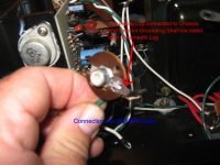
Fab would you commented this picture, input GND connection are Musical Concept ground modification, I would say input GND connects to the screw that is in fact mount electrolytic capacitors and then goes on to GND BUS what do you think?
An externally hosted image should be here but it was not working when we last tested it.
Last edited:
I found a good place for Mundorf input capacitors.
An externally hosted image should be here but it was not working when we last tested it.
Last edited:
Thank you eyoung, I always wonder if something else I can do in order to make this great device for even better.
Fab would you commented this picture, input GND connection are Musical Concept ground modification, I would say input GND connects to the screw that is in fact mount electrolytic capacitors and then goes on to GND BUS what do you think?
An externally hosted image should be here but it was not working when we last tested it.
Hi Stenks
Input GND on pcb should connect to RCA GND. Input Shield should be connected only on respective left and right RCA GND and not terminated at the pcb. I would connect also a GND lifter (back-to-back 5 or 10A diode in // with resistor of about 20 ohms 3w or so) between the GND BUS and chassis - provided that you use a power cable with chassis GND.
Nice location for your input cap. Can you comment on the sound difference after using Mundorf input cap. What value used?
Also for your GND BUS I would use the Musical Concept way to have a different connection point for the transfo gnd which is noisy....
Fab
Last edited:
Hi Fab
I'll try to convey how well this all sounds but as you will see in the footage is pretty bad because it was recorded on camera, video camera battery was empty and we've made this in a hurry. Now I will try to describe in a few words how it sounds, transparent, neutral and easy to listen to.
Listen to the link below:
Hafler DH 200 Power amp Hafler DH 101 Preamp & Acoustic Research AR 25 Speaker - YouTube
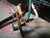
I want to upgrade the RCA input connectors on my DH-200. While taking apart the old tin-connectors I noticed that the left-channel grounding lug of the connector is connected to the chassis via a resistor. I also noticed that the exterior grounding shell itself is directly connected to the chassis. See pics below:


When I install the new RCA jack should I solder the resistor between the new grounding ring on the connector and the chassis? I'm not sure this will be the same circuit connection as the old one because the old exterior grounding shell was directly connected to the chassis. The new RCA connectors are designed to keep the exterior shell isolated from the chassis via spacers.
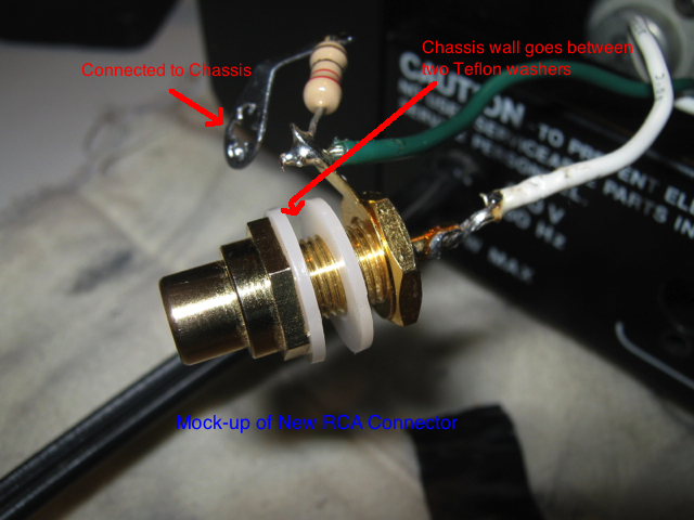
Not sure what I should do. Can I just forego the resistor altogether and just wire it up the normal way (green wire to ground lug/white wire to center pin)? Or should I wire it like the pic above?
When I install the new RCA jack should I solder the resistor between the new grounding ring on the connector and the chassis? I'm not sure this will be the same circuit connection as the old one because the old exterior grounding shell was directly connected to the chassis. The new RCA connectors are designed to keep the exterior shell isolated from the chassis via spacers.
Not sure what I should do. Can I just forego the resistor altogether and just wire it up the normal way (green wire to ground lug/white wire to center pin)? Or should I wire it like the pic above?
Attachments

Many years ago, I cascoded the input diff stage and it was a good improvement that you could hear.
someone please correct me if I'm wrong but the resistor to ground to separate input to chassis ground to keep hum out of input...I have used it on all the haflers I've had and will continue...
In response to Mr. Marsh(like your avatar) Fab did a low TIM (ifaik) diagram way back in this thread I would have an interest in this modification if I had a recommendation for transistors, Fab showed pictures of his mods in this thread also...Really cool stuff.
Regards, El
In response to Mr. Marsh(like your avatar) Fab did a low TIM (ifaik) diagram way back in this thread I would have an interest in this modification if I had a recommendation for transistors, Fab showed pictures of his mods in this thread also...Really cool stuff.
Regards, El
The input jacks were moved and grounding on the 220 changed to eliminate this insulator and resistor.
I suggest using a reversed polarity parallel diode pair (1N4000x OK) to prevent this resistor from failing, as it frequently does. A 0.1µF film cap should also be in parallel with the resistor-diode pair.
I suggest using a reversed polarity parallel diode pair (1N4000x OK) to prevent this resistor from failing, as it frequently does. A 0.1µF film cap should also be in parallel with the resistor-diode pair.
- Home
- Amplifiers
- Solid State
- Hafler DH-200/220 Mods