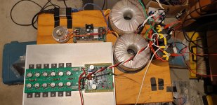
Ok So I built a 6 pair board. (Not sure if this is the appropriate thread or the DH500C thread)
It is working with +/- 93 Vdc rails and a dozen Exicon dual die matched laterals.
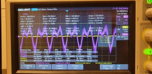
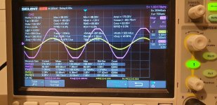
Only problem is I have a low level parasitic oscillation which increases with bias.(pictured)
The amp is working apart from this.... If any one has any tips let me know.
I have tried wiring layout, gate stoppers, snubbing the large electrolytics...
Different gate stopper resistors (both smd and through hole)
The low level oscillation is ruining the excellent thd performance I had with Rick Savas 3 pair boards.
It is working with +/- 93 Vdc rails and a dozen Exicon dual die matched laterals.
Only problem is I have a low level parasitic oscillation which increases with bias.(pictured)
The amp is working apart from this.... If any one has any tips let me know.
I have tried wiring layout, gate stoppers, snubbing the large electrolytics...
Different gate stopper resistors (both smd and through hole)
The low level oscillation is ruining the excellent thd performance I had with Rick Savas 3 pair boards.
Attachments
That is one aggressive output stage. Curious, why do you think you need that amount of output current?
I have a few ideas on oscillation
1) simulate but one needs models for those fets. Are two single die really equal to a dual die? In my initial proto I used one set dual die, it was fine.
2) try to back off on the amount of fet pairs, start with one pair, see if it oscillates with one pair and go up one pair at a time from there
3) using that amount of dual dies adds a lot of capacitance to the drivers. I am wondering if the driver current needs to be increased to compensate. Iirc Bob used stronger driver bias initially, 33 ohms but it was increased to 47 since it was determined it was not needed and could run fine having a lower power dissipated in the drivers.
4) Bob shows some tricks in his book on adding Zobels to the gate/drains.
Will ask Bob what he thinks
Hi Rick,
Thanks for your input on this, for what it is worth your 3 pair board design performed very well in both measured output power and measured THD. It is a credit to your layout skills. I neglected to use thermal relief on mine on the advice of some friends which was a mistake in hindsight...
The reasons I am working on this amount of output devices is because I have a relatively expensive set of toroidal transformers I would like to use for this project and I like to have to have the option of using my amplifiers for party or small venue use occaisionally. - Also just for fun!
I have the LTspice file for the front end - I did measure the predriver current at 20 kHz with 3 pairs but it looks like the load may be increasing more than expected with 6 pairs.
I may be able to increase pre driver current without too much drama and see the results.
-Dan
Hi Dan
I forget, Did you use those dual die fets in DH-500c(ops)?
Couple more thoughts on your mega ops
You could try disabling the fets, remove the gate R and connect gate to source. Try enabling the ones closest to afe and then furthest away.
Sometimes having a load will tame the oscillations. More testing and experiments
Good luck
Rick
Ok So I built a 6 pair board. (Not sure if this is the appropriate thread or the DH500C thread)
It is working with +/- 93 Vdc rails and a dozen Exicon dual die matched laterals.
Only problem is I have a low level parasitic oscillation which increases with bias.(pictured)
The amp is working apart from this.... If any one has any tips let me know.
I have tried wiring layout, gate stoppers, snubbing the large electrolytics...
Different gate stopper resistors (both smd and through hole)
The low level oscillation is ruining the excellent thd performance I had with Rick Savas 3 pair boards.
I'm sorry to hear you are having these parasitic oscillation troubles with this large number of output pairs. You are in somewhat uncharted waters here. First of all, sometimes these oscillations are hard to see and sometimes they are just bursts on a part of the waveform. Sometimes they just occur under certain load conditions. So bravo to you for at least discovering them!
Such oscillations with MOSFETs can be extremely hard to track down. I've had the same kinds of problems at times. One time I tried to get away with smaller gate stoppers, but got oscillations and was never able to cure them. When doing my MOSFET power amplifier in the early 80s, I did come up with a scheme where I put Zobel networks between the gate and drain (or ground, I don't remember) of each output device. They were vertical MOSFETs, which are even faster than laterals. That article is on my website at cordellaudio.com. These things often come down to parastic inductances that exist somewhere, even sometimes inside the MOSFET device. A Zobel in the right place can potentially damp resulting resonances.
Did these oscillations exist with no load, or was the amplifier loaded? What things did you try with the base stopper resistors?
Cheers,
Bob
Watch out that the output zobel caps don’t get damaged by the ossicilation current
Last edited:
I have had problems with oscillations on a couple of amps with J55/K175.
A C0G cap soldered between gate and drain solved it. Values on the one with six pairs was 220p on J55, and 470p on K175. It looks like a lot, but I have approximately 100 PCB's for 4 pairs TO3 laying here, so... I guess that they're not the best 😕
Anyway, I could not measure any difference in THD or slewrate.
But it sounds a bit better without oscillations 🙂
BR
Figge
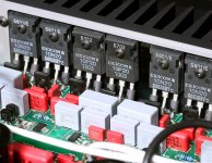
Gate to Drain Cap on each of the N Channel MOSFETs
Hi Dan. Similar to Trollet’s post, I was going to suggest installing 33 pF mica caps on the gate to drain of each of the N channel MOSFETs. Erno Borbely (designer of the Hafler DH-200), incorporated this in his later Servo amp designs to help stability (http://schematic.narod.ru/Audio/semi/Amp/servo50.pdf). This has been covered in previous posts in this Hafler DH-200/220 Mods thread (e.g., refer to post #198). Bob Cordell agrees this should help stability per post #1733. I’ve incorporated this in my DH500 build installing the mica caps directly on the gate to drain legs on each of the N channel MOSFET sockets. In your case, I guess the caps would need to be installed on your OPS board as close to the N channel MOSFETs as possible. Good luck, Bill.
Hi Dan. Similar to Trollet’s post, I was going to suggest installing 33 pF mica caps on the gate to drain of each of the N channel MOSFETs. Erno Borbely (designer of the Hafler DH-200), incorporated this in his later Servo amp designs to help stability (http://schematic.narod.ru/Audio/semi/Amp/servo50.pdf). This has been covered in previous posts in this Hafler DH-200/220 Mods thread (e.g., refer to post #198). Bob Cordell agrees this should help stability per post #1733. I’ve incorporated this in my DH500 build installing the mica caps directly on the gate to drain legs on each of the N channel MOSFET sockets. In your case, I guess the caps would need to be installed on your OPS board as close to the N channel MOSFETs as possible. Good luck, Bill.
Thanks to everyone who took the time to reply it is appreciated !
Hi Rick, yes I am using dual die fets (factory matched ECW20N20-S, ECW20P20-S) your DH500C OPS board performed very well with these.
Hi Bob, These oscillations are present with no load and no input signal.
I have tried both surface mount and through hole gate stoppers in case there was a voltage coefficient problem, I have also tried alternate wiring, alternate Zobel network values, alternate grounding for the heatsink and alternate earth wiring and snubbing for the large psu electrolytics incase it was ringing eminating from there, to no avail at this point. I have the article I will revisit it and check out the Zobel configuration - Thanks for the tip Bob
At this point I will try some of the suggestions and report back
Thanks again guys
-Dan
Hi Dan
I forget, Did you use those dual die fets in DH-500c(ops)?
Couple more thoughts on your mega ops
You could try disabling the fets, remove the gate R and connect gate to source. Try enabling the ones closest to afe and then furthest away.
Sometimes having a load will tame the oscillations. More testing and experiments
Good luck
Rick
Hi Rick, yes I am using dual die fets (factory matched ECW20N20-S, ECW20P20-S) your DH500C OPS board performed very well with these.
I'm sorry to hear you are having these parasitic oscillation troubles with this large number of output pairs. You are in somewhat uncharted waters here. First of all, sometimes these oscillations are hard to see and sometimes they are just bursts on a part of the waveform. Sometimes they just occur under certain load conditions. So bravo to you for at least discovering them!
Such oscillations with MOSFETs can be extremely hard to track down. I've had the same kinds of problems at times. One time I tried to get away with smaller gate stoppers, but got oscillations and was never able to cure them. When doing my MOSFET power amplifier in the early 80s, I did come up with a scheme where I put Zobel networks between the gate and drain (or ground, I don't remember) of each output device. They were vertical MOSFETs, which are even faster than laterals. That article is on my website at cordellaudio.com. These things often come down to parastic inductances that exist somewhere, even sometimes inside the MOSFET device. A Zobel in the right place can potentially damp resulting resonances.
Did these oscillations exist with no load, or was the amplifier loaded? What things did you try with the base stopper resistors?
Cheers,
Bob
Hi Bob, These oscillations are present with no load and no input signal.
I have tried both surface mount and through hole gate stoppers in case there was a voltage coefficient problem, I have also tried alternate wiring, alternate Zobel network values, alternate grounding for the heatsink and alternate earth wiring and snubbing for the large psu electrolytics incase it was ringing eminating from there, to no avail at this point. I have the article I will revisit it and check out the Zobel configuration - Thanks for the tip Bob
- I agree, no damage at this point (250 V, 0.022 uF rating)Watch out that the output zobel caps don’t get damaged by the ossicilation current
- I agree, no damage at this point. (3W, 16 Ohm x 3 distributed Zobel)I think the resistor rather than the capacitor needs to be watched.
Best regards!
Thanks Figge, I am yet to try this....I have had problems with oscillations on a couple of amps with J55/K175.
A C0G cap soldered between gate and drain solved it. Values on the one with six pairs was 220p on J55, and 470p on K175. It looks like a lot, but I have approximately 100 PCB's for 4 pairs TO3 laying here, so... I guess that they're not the best 😕
Anyway, I could not measure any difference in THD or slewrate.
But it sounds a bit better without oscillations 🙂
BR
Figge
Thanks for the link Bill, your input on the DH500C has been very helpful, I am yet to try this approach but it sounds promising.Hi Dan. Similar to Trollet’s post, I was going to suggest installing 33 pF mica caps on the gate to drain of each of the N channel MOSFETs. Erno Borbely (designer of the Hafler DH-200), incorporated this in his later Servo amp designs to help stability (http://schematic.narod.ru/Audio/semi/Amp/servo50.pdf). This has been covered in previous posts in this Hafler DH-200/220 Mods thread (e.g., refer to post #198). Bob Cordell agrees this should help stability per post #1733. I’ve incorporated this in my DH500 build installing the mica caps directly on the gate to drain legs on each of the N channel MOSFET sockets. In your case, I guess the caps would need to be installed on your OPS board as close to the N channel MOSFETs as possible. Good luck, Bill.
At this point I will try some of the suggestions and report back
Thanks again guys
-Dan
Ok So I built a 6 pair board. (Not sure if this is the appropriate thread or the DH500C thread)
It is working with +/- 93 Vdc rails and a dozen Exicon dual die matched laterals.
Only problem is I have a low level parasitic oscillation which increases with bias.(pictured)
The amp is working apart from this.... If any one has any tips let me know.
I have tried wiring layout, gate stoppers, snubbing the large electrolytics...
Different gate stopper resistors (both smd and through hole)
The low level oscillation is ruining the excellent thd performance I had with Rick Savas 3 pair boards.
Maybe the resistors are to far away from the gate. The double die exicons are extremely prone to oscillations if gate leg length to resistor is more as a few millimeters. Have had nearly the same problems during development off a 3 pair exicon design where I now sucessfully use 270R (N) and 180R (P) gate resistors.
If you can't change your layout try to use ferrit beads.
BR, Toni
ferrite use in Goldmund designs
I am glad that you mentioned this Toni... Closely studying Goldmund designs,
I see "little" things that they are doing collectively to benefit sum of the parts, chassis,
circuit layout and treatment... as a no holds barred build.
Seeing images (#1) in the past like this one, has had me wondering about Ferrite Beads
on the gate and Drain leads, considering using *ferrite loading* on my Exicons...
**It is ~also~ nice to see local film bypasses on each output device...
Prudent engineering overkill *typical* of Goldmund...
These recently released Musical Concepts PA8 driver cards (#2)
have mounting holes, for outputs direct to the PCB assembly...
with gate (added source) resistors, it is really brilliant...
excited about installing them.
~ output stage loading ~
The Gate and Source lead resistor loading adjustment consideration(s),
is one that I also agree with. (#3) I am very happy with 1,000 ohm
on the gate and .33 on the source. EG. no mica caps used/needed.
*Note the parts, as shown *are tacked* in place,
to confirm routing, clearance and placement...
.solder never "looks right'" in photos.
The work almost looks shoddy...
Maybe the resistors are to far away from the gate. The double die exicons are extremely prone to oscillations if gate leg length to resistor is more as a few millimeters. Have had nearly the same problems during development off a 3 pair exicon design where I now sucessfully use 270R (N) and 180R (P) gate resistors.
If you can't change your layout try to use ferrit beads.
BR, Toni
I am glad that you mentioned this Toni... Closely studying Goldmund designs,
I see "little" things that they are doing collectively to benefit sum of the parts, chassis,
circuit layout and treatment... as a no holds barred build.
Seeing images (#1) in the past like this one, has had me wondering about Ferrite Beads
on the gate and Drain leads, considering using *ferrite loading* on my Exicons...
**It is ~also~ nice to see local film bypasses on each output device...
Prudent engineering overkill *typical* of Goldmund...
These recently released Musical Concepts PA8 driver cards (#2)
have mounting holes, for outputs direct to the PCB assembly...
with gate (added source) resistors, it is really brilliant...
excited about installing them.
~ output stage loading ~
The Gate and Source lead resistor loading adjustment consideration(s),
is one that I also agree with. (#3) I am very happy with 1,000 ohm
on the gate and .33 on the source. EG. no mica caps used/needed.
*Note the parts, as shown *are tacked* in place,
to confirm routing, clearance and placement...
.solder never "looks right'" in photos.
The work almost looks shoddy...
Attachments

Maybe the resistors are to far away from the gate. The double die exicons are extremely prone to oscillations if gate leg length to resistor is more as a few millimeters. Have had nearly the same problems during development off a 3 pair exicon design where I now sucessfully use 270R (N) and 180R (P) gate resistors.
If you can't change your layout try to use ferrit beads.
BR, Toni
Thanks Toni, I appreciate the input, and I also should mention your designs & layouts look very neat !
I have tried directly attaching the gate stoppers to the gate lead. This did not solve the problem but was worth testing.
I returned to smd gate stoppers about 4-5 mm from the transistor leg.
I am glad that you mentioned this Toni... Closely studying Goldmund designs,
I see "little" things that they are doing collectively to benefit sum of the parts, chassis,
circuit layout and treatment... as a no holds barred build.
Seeing images (#1) in the past like this one, has had me wondering about Ferrite Beads
on the gate and Drain leads, considering using *ferrite loading* on my Exicons...
**It is ~also~ nice to see local film bypasses on each output device...
Prudent engineering overkill *typical* of Goldmund...
These recently released Musical Concepts PA8 driver cards (#2)
have mounting holes, for outputs direct to the PCB assembly...
with gate (added source) resistors, it is really brilliant...
excited about installing them.
~ output stage loading ~
The Gate and Source lead resistor loading adjustment consideration(s),
is one that I also agree with. (#3) I am very happy with 1,000 ohm
on the gate and .33 on the source. EG. no mica caps used/needed.
*Note the parts, as shown *are tacked* in place,
to confirm routing, clearance and placement...
.solder never "looks right'" in photos.
The work almost looks shoddy...
Thanks for the input, I am trying not to increase the gate stoppers to retain some of the output stage speed to help keep THD low.
-Dan
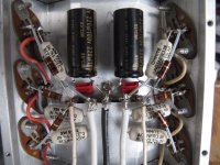
Parasitic Oscillation fixed!
Hi Guys,
Thanks for all the suggestions.
It was a two part solution to this problem.
First, on Bob's suggestion I added an RC network to the gate circuit on the output stage board. On both the P and N gate tracks to earth 68pF silver mica + 100 Ohm solved the low level parasitic oscillation at idle.
Second, on Bill and Figge's suggestions (per Erno Borbely circuit) I added
~33 pF (I used series 68pF NPO for voltage rating) on each N channel mosfet gate to drain which completely got rid of the burst parasitic oscillation which was present with signal.
So it looks like the N channel side is a little fast at 16pF Crss and the 33pF tames it.
I am very happy now, the performance is back up there!
Thanks all who contributed suggestions it was really helpful.
Attachments

Hi Guys,
Thanks for all the suggestions.
It was a two part solution to this problem.
First, on Bob's suggestion I added an RC network to the gate circuit on the output stage board. On both the P and N gate tracks to earth 68pF silver mica + 100 Ohm solved the low level parasitic oscillation at idle.
Second, on Bill and Figge's suggestions (per Erno Borbely circuit) I added
~33 pF (I used series 68pF NPO for voltage rating) on each N channel mosfet gate to drain which completely got rid of the burst parasitic oscillation which was present with signal.
So it looks like the N channel side is a little fast at 16pF Crss and the 33pF tames it.
I am very happy now, the performance is back up there!
Thanks all who contributed suggestions it was really helpful.
This is great news, Daniel, and it is helpful to all of us. Congratulations and kudos for your persistence in solving this problem.
Cheers,
Bob
This is great news, Daniel, and it is helpful to all of us. Congratulations and kudos for your persistence in solving this problem.
Cheers,
Bob
Hi Bob,
Thanks for the positive feedback, it means alot coming from someone like yourself.
Best regards
- Dan
Dan, that is great news! May I ask what gate stopper resistor values you currently have? It would be interesting to know if there is room to reduce the gate resistors with the modifications you’ve made. Erno Borbely used 220 ohms in his Servo amp design for both N and P channels. Bill.
- Home
- Amplifiers
- Solid State
- Hafler DH-200/220 Mods