Hello! Could someone help me with this amp. GroundZero 1.1200dx-ii monoblock. Protection light is right on and nothing happends. Measured all fets etc, no problem found. TL494 pins 9 and 10 measure 0volts so there is no pwm at outputs eather. Changed the TL494 but no help. What could cause this, any ideas?
Attachments
I don't have anything really close. Post the voltages on all terminals of the 494. Copy and paste the following list and fill in the blanks.
Pin 1:
Pin 2:
Pin 3:
Pin 4:
Pin 5:
Pin 6:
Pin 7:
Pin 8:
Pin 9:
Pin 10:
Pin 11:
Pin 12:
Pin 13:
Pin 14:
Pin 15:
Pin 16:
Pin 1:
Pin 2:
Pin 3:
Pin 4:
Pin 5:
Pin 6:
Pin 7:
Pin 8:
Pin 9:
Pin 10:
Pin 11:
Pin 12:
Pin 13:
Pin 14:
Pin 15:
Pin 16:
Pin 1: 2,81
Pin 2: 4,48
Pin 3: 4,71
Pin 4: 3,95
Pin 5: 1,43
Pin 6: 3,65
Pin 7: 0,00
Pin 8: 11,98
Pin 9: 0,00
Pin 10: 0,00
Pin 11: 11,98
Pin 12: 11,19
Pin 13: 5,00
Pin 14: 5,00
Pin 15: 5,00
Pin 16: 8,12
Pin 2: 4,48
Pin 3: 4,71
Pin 4: 3,95
Pin 5: 1,43
Pin 6: 3,65
Pin 7: 0,00
Pin 8: 11,98
Pin 9: 0,00
Pin 10: 0,00
Pin 11: 11,98
Pin 12: 11,19
Pin 13: 5,00
Pin 14: 5,00
Pin 15: 5,00
Pin 16: 8,12
Pin 16 is driving it into protect. Lifting that pin and grounding it may get the amp to power up enough to see what problem is driving it into protect.
You'll have to be careful since the protection is going to be disabled.
Have you tried to get a diagram from GZ? Sometimes, those outside of the US have a better chance of getting the diagram than we in the US do.
You'll have to be careful since the protection is going to be disabled.
Have you tried to get a diagram from GZ? Sometimes, those outside of the US have a better chance of getting the diagram than we in the US do.
Last edited:
Okay thank you Perry. I did what you told me and the amp powers up. Nothing drama happened, no dc at outputs, rail voltages ok and so on. But..with 1V/50Hz sine I didn't get anything at output. Seems like the signal is migging from output fets.
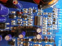
Think that U509 (in the picture) could be IR2010?? If so, then at pins 1 and 8 (HO and LO) is coming nothing out.
Think that U509 (in the picture) could be IR2010?? If so, then at pins 1 and 8 (HO and LO) is coming nothing out.
With the black probe on the negative rail, post the DC voltage on all terminals of the 2010. Use the same list of pin numbers that you used last time.
Okay took time to get measured but now I got the results 👍
Pin 1: 0,00
Pin 2: 0,00
Pin 3: 12,40
Pin 4: 0,06
Pin 5: 0,06
Pin 6: 48,3
Pin 7: 47,9
Pin 8: 48,0
Pin 9: 0,01
Pin 10: 0,01
Pin 11: 5,01
Pin 12: 2,30
Pin 13: 4,49
Pin 14: 2,71
Pin 15: 0,00
Pin 16: 0,00
Pin 1: 0,00
Pin 2: 0,00
Pin 3: 12,40
Pin 4: 0,06
Pin 5: 0,06
Pin 6: 48,3
Pin 7: 47,9
Pin 8: 48,0
Pin 9: 0,01
Pin 10: 0,01
Pin 11: 5,01
Pin 12: 2,30
Pin 13: 4,49
Pin 14: 2,71
Pin 15: 0,00
Pin 16: 0,00
The shutdown pin is high. This is shutting down the output of the IC. You could try lifting that pin. It should pull down (internally) and the IC should produce output.
Again, be careful. There may be a legitimate problem that's causing the IC to be shut down.
Again, be careful. There may be a legitimate problem that's causing the IC to be shut down.
Okay, I'll try that. Do you have any ideas what could cause the problem? Where I could look for faulty parts
Yes. Pin 13.
Sometimes, there is a legitimate problem that's triggering the shutdown. Other times, the protection circuit has a fault. Without a diagram, you have to try defeating the protection if there are no obvious problems.
Sometimes, there is a legitimate problem that's triggering the shutdown. Other times, the protection circuit has a fault. Without a diagram, you have to try defeating the protection if there are no obvious problems.
Has the voltage on pins 12 and 14 changed significantly?
Post the DC voltage on all terminals of U107.
Only power up for a few seconds at a time to prevent doing more damage.
I didn't state this earlier but n some instances, the 494 will not function properly when a distant ground point is used. Grounding to pin 7 is less likely to cause problems. If you have some old stranded computer ribbon cable that you can use for a jumper, it's less likely to break the pin on the IC.
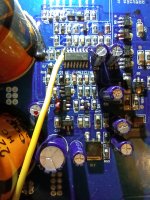
I don't see Q12.
Post the DC voltage on all terminals of U107.
Only power up for a few seconds at a time to prevent doing more damage.
I didn't state this earlier but n some instances, the 494 will not function properly when a distant ground point is used. Grounding to pin 7 is less likely to cause problems. If you have some old stranded computer ribbon cable that you can use for a jumper, it's less likely to break the pin on the IC.
I don't see Q12.
I'll measure these tomorrow but couple things..U107 measure with black probe where? Q12 is at bottom of the latest picture.
On the secondary ground. That can be either the secondary center tap or (generally) the negative speaker terminal.
From post 15:
Has the voltage on pins 12 and 14 changed significantly?
The 10 ohm resistor in front of the base leg of Q12 is what smoked.
Has the voltage on pins 12 and 14 changed significantly?
The 10 ohm resistor in front of the base leg of Q12 is what smoked.
- Home
- General Interest
- Car Audio
- GZTA 1.1200